Download
1 / 8
100 likes | 491 Views
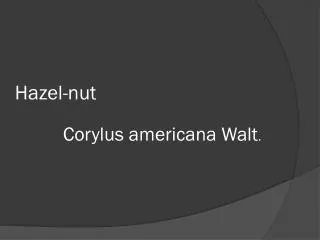
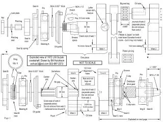
Big end brg. Oil hole. Seal A. Shim 0.037 “ thick. M24 x 1.5. Lathe center-drill feature. Pin. Flush. Clutch. Lock plate. Key, 5.0 mm wide. Nut. Pilot brg. Journal of web 2 (separate piece) Do not remove from web 2. 0.695”. 30 mm.

E N D
Big end brg Oil hole Seal A Shim 0.037 “ thick M24 x 1.5 Lathe center-drill feature Pin Flush Clutch Lock plate Key, 5.0 mm wide Nut Pilot brg Journal of web 2 (separate piece) Do not remove from web 2 0.695” 30 mm Rod (“Made in Japan” on both rods faces Dynastart end of crank -- but it may not matter) Crank stub of web 1 Pilot brg seal Grease space Seal A race Bearing A 10.0 mm force fit 10.0 mm sliding fit Oil guide Seal lip spring Web 2 Web 1 * Piston pin brg * One piece Exploded view of 1972 L50 Suzuki crankshaft. Drawn by Bill Hutchison wchutc3@aol.com 502-897-2373 Ring Qty: 2 NOT TO SCALE 1.920” 10.0 mm Alignment holes Seal B Shim 0.037 “ thick Serrations Groove Gap Slide fit Force fit Pin M10 x 1.50 Pin Pin Center-drill C-clip Center-drill Rod and rod brgs not shown No gap Distributor drive gear Journal of web 3 (separate piece) Do not remove from web 3 30 mm Crank stub of web 3 (separate piece) Do not remove from web 3 -- believed to be shrunk fit 0.0914 to 0.915 inches C-clip ears Bearing B Brg C Brg D Seal D Oil guide Seal B race Web 3 Web 4 Seal C Oil hole Flush Seal C race Exploded on next page
NOT TO SCALE This piece goes in oil pump side of crankcase Piston pin brg Crescent retainer One piece C-clip groove Groove for crescent retainer Force fit Rod Pin M10 x 1.50 Pin Distributor drive gear C-clip 35 mm 25 mm Ears Dynastart Seal C race Brg C Brg D Seal D Web 4 All bearing anti-rotate pins go in oil pump side of crankcase. Seal C Big end brg Drawing notes 1. Some features like oil holes and C-clip ears and the woodruff key are not shown clocked in the correct angular position for clarity. The clutch woodruff key position is not alterable. The oil holes for the rod big ends should be placed so that their open ends point approximately 180 degrees away from the crankshaft centerline (to obtain the best effect from centrifugal force.) C-clip ears should point either towards or away from the crankshaft centerline to lessen the loosening effect of centrifugal force (I do not know which position is better for balancing). 2. The side of the pilot bearing seal with the spring (that holds tension on the seal lip) should be installed to face the pilot bearing. 3. Pilot bearings have a rounded end and a square end. The rounded end should be installed into the bore in the web 1 crank stub as shown. 4. Seal races are shown the same width as seals. In reality they are somewhat wider than their mating seals. The seal races are medium force fits and are installed hard against whatever is adjacent to them. Therefore, there is not enough clearance behind them, usually, to engage a bearing splitter. In this case, for seal race C, use a brass drift through a crankweb balancing hole to dislodge the race enough to engage a splitter or puller behind it. 5. Seal A and C have the same basic dimensions (except that seal C is 2 mm wider) and would apparently interchange. However, seal A is made with much more rubber than seal C (which is mostly formed from sheet metal) and they have different Suzuki part numbers. Perhaps seal C runs hotter than seal A or maybe one of these seals has been replaced. I do not know . 6. The large crankweb balancing holes adjacent to the con rod journal holes are not shown in the drawings for clarity. See page 4 for pictures of the balancing holes.
Crankshaft disassembly Douse all joints with penetrating oil before attempting to separate the crankshaft. It may not be necessary but it cannot hurt. 1. Remove seal D. Write down all numbers on seal ____________________. Carefully measure distance from dynastart-end of shaft to bearing D. Use a dial caliper or depth micrometer. (Mine measured 1.920 inches.) Write this dimension down ____________________. 2. Use a two or three arm puller to remove Bearing D. If a bearing is to be reused, it should never be pulled by its OD but here I am assuming that the old bearings are to all be replaced. Write down numbers on bearing D ____________________. 3. Remove C-clip adjacent to bearing C. Note position of ears ____________________. 4. Bearing splitters come in about three sizes. The middle size is perfect for L50 crankshaft work. A medium-sized splitter by K-D Tools (P/N 2264) is pictured on page 4. Engage your splitter in the groove of bearing C (or behind it, adjacent to seal C) and remove bearing C with a two-arm puller. The splitter should not be torqued together. In other words, tighten the splitter so that it will not shift or move during pulling but not so tight as to damage anything. Write down numbers on bearing C ____________________. 5. Remove seal A. Write down numbers on seal A ____________________. 6. Engage the splitter between bearing A and the adjacent oil guide. Only about 1/32” of the splitter lips will engage behind bearing A. Tighten the splitter with fingers only else the oil guide will be bent. Carefully attach a two-arm puller and make sure everything a square for a straight pull. Use an electric impact wrench to tighten the puller to avoid putting stresses on the puller that might make it slip. If the bearing does not seem to move after a few turns of the puller screw, remove the impact wrench and strike the head of the puller screw with a steel hammer. This will loosen the joint. Continue with the impact wrench. Bearing A should pull off along with seal race A. Write down numbers on bearing A ____________________. 7. Measure clearance between both big end bearings and the adjacent wall of the crankweb. (They should both be about 0.025 inches). Write this information down. Clutch-end rod bearing clearance ____________________. Dynastart-end rod bearing clearance ____________________. 8. Either end-most crank web removes the same way. Use a small two-arm puller through the crankweb balancing holes adjacent to the rod journals as shown on page 4. This will be a tight fit for most pullers. Position puller arms as shown on page 4 where the claws of the puller arms point away from each other. Pack the puller arms in the balancing holes with stray bolts or whatever. This will keep the arms from slipping off the small ledge they have available. Put a nice smooth socket between the puller screw and the rod journal so that the journal bore in the crank web will not be harmed. Note: the socket will be somewhat off center on the rod journal -- make sure that it bears only on the rod journal. Use the impact wrench and hammer if needed. I have not observed any numbers on any rod bearings (big-end or little-end). However, write down any you may find. Clutch-end: ______________ Dynastart-end: _____________ Also write down the width of the big-end bearings (new bearings may measure different) Clutch-end: ____________________ Dynastart-end: ____________________. When reassembling, this width plus the clearance (step 7) must remain the same. Increase or decrease the clearance to compensate. 9. Repeat step 8 for other end-most crankweb. 10. Carefully position a large two-arm puller on web 2 and push out the crank stub of web 3 along with web 3 itself. Use the impact wrench and hammer technique as before. This joint is a tighter fit than the others so use care and be prepared for the impact wrench to do lots of work. I cannot recommend a three-arm puller due to the relief in the web for the con rod. 11. Remove seal B. I have not seen any numbers on seal B (except it is marked “Ars” or “Ays”. I assume this is the manufacturer). Write down any that you may find ____________________. 12. Repeat step 6 for seal race B and bearing B. Write down all numbers on bearing B ____________________. Your crank is as apart as it needs to be. 13. Go off to the bearing store to shop for all the bearings and seals you removed. See if they can provide oversize big- and little-end bearings for the connecting rods, if needed. 14. Thoroughly clean all nooks and crannies where centrifugal force has packed in crud for all these many years -- especially the inside rim of the oil guides and all oil passages. More later when I get replacement parts and reassemble my crank!!!! I plan on filling the crankweb balancing and alignment holes with balsa wood for increased crankcase compression -- an old two-stroke racing trick. Note on seal race B: The Internal Diameter (ID) of seal B should show almost zero wear. The rings are designed to rotate in the groove of seal race B. Therefore, the rings remain motionless with respect to seal B. If all is well, seal B and seal race B should not need replacement.
K-D Tools bearing splitter part number 2264. Cost: about $60. Upright bolts are 5/8-18 threaded. Be sure they are the same length for straight pulling. And count turns if you adjust their length. Splitter with Sears-Roebuck brake drum puller from mid 1950’s. Holes in puller claws eliminate slipping. Avoid using this type of puller claw with splitter. It will surely slip and makes adjusting for a straight pull difficult. The claws are rarely wide enough for a 5/8” bolt anyway. Crankweb balancing hole Web 3 Web 4 Staged photograph. Con rod is already removed. Journal Claw Claw Socket Packing Packing Crankweb balancing hole Pulling web 4. Cardboard protects distributor drive gear. More cardboard under screw to protect crank stub should also be used. Be sure that puller claws do not stress con rod. Close-up view from photo at left. Old lathe bits used for packing to keep arms of puller from slipping. Smooth surface of socket protects journal bore from scratches. Use oil as well.
Data Vehicle 1972 Suzuki LJ20VL Brute Body number 108469 Engine L50 (359 cc nominal), bored 0.5 mm over Engine number 192488 Odometer 23,763 miles Crankshaft Bearing anti-rotate pins Roll-pins, 2.5 mm OD x 5 mm long (0.10 x 0.205 inches) Clutch nut 32 mm across flats, 10 mm thick (called a Low nut, referring to thinness), M24 x 1.5 Pilot bearing seal No markings. 10 mm ID x 15 mm OD x 5 mm (0.210 inches) wide. Seal can be somewhat wider if needed. Pilot bearing Enclosed needle roller bearing. Markings : HKS 10x15x15 INA-NTN Dimensions: 10 mm ID x 15 mm OD x 15 mm long Seal A race Medium force fit onto shaft. Nominal dimensions : 30 mm ID x 44 mm OD x 12.5 mm wide. Seal A Markings : NOK AH6864E 4.6 Dimensions : 72 mm OD x 44 mm ID x 8 mm thick. Flange : 76 mm OD x 1 mm thick. Bearing A Markings : KOYO 83555-9 Dimensions : 72 mm OD x 30 mm ID x 20 mm wide. Shoulder : 65 mm OD x 3.7 mm deep. Oil guide shims Both shims are the same. Dimensions : 43 mm OD x 30.5 mm ID x 0.037 inches thick. Big-ends Bearings not marked. Clearance twixt bearing and web: 0.025 inches. Width : 0.695 inches. Big end journal : 0.914 to 0.915 inches OD. Big-end bore : 1.272 inches. Little-ends Bearings not marked. Width : 0.932 inches. Piston-pin OD : 0.627 to 0.628 inches. Little-end bore : 0.788 inches Seal B race No markings. Dimensions : 1.714 inches OD x 25 mm ID x 0.454 inches wide. Groove width : 0.118 inches Seal B race rings 46 mm (1.811 inches) OD uncompressed, 1.651 inches ID uncompressed, ring thickness (each) : 0.057 inches, Gap when compressed in seal B: about 0.010 inches. Seal B Markings : “Ars” or perhaps “Ays”. It is hard to read. No other markings. Dimensions : 72 mm OD x 44 mm ID x 8 mm wide. Flange : 76 mm OD x 1 mm thick. Bearing B Markings : KOYO 83555-9 Dimensions: 72 mm OD x 30 mm ID x 20 mm wide. Shoulder : 65 mm OD x 3.7 mm deep. Seal C race Medium force fit onto shaft. Nominal dimensions : 44 mm OD x 35 mm ID x 11.2 mm wide. Seal C Markings : NOK DC5Y44 72 6.7 8.7 1.5 Dimensions: 72 mm OD x 44 mm ID x 10 mm thick. Flange : 76 mm OD x 1 mm thick. Bearing C Markings : KOYO 83553-9R Dimensions: 72 mm OD x 35 mm ID x 17 mm wide. Groove : 0.070 inches deep x 0.080 inches wide x 0.123 inches from face of bearing. Crescent retainer Dimensions : 79 mm OD x 69 mm ID x 0.070 inches thick, arc : about 170 degrees C-clip Dimensions: 32 mm ID, 0.057 inches thick Distributor drive gear Need to define this, just in case. Bearing D Markings : HIC 83464 Dimensions: 62 mm OD x 25 mm ID x 17 mm wide. Seal D (race is crankshaft) Markings : “Ars” or perhaps “Ays” “Japanese character (see page 7)” SD-2552 10-R B1 Dimensions: 52 mm OD x 25 mm ID x 10 mm wide. Flange : 55 mm OD x 1 mm thick. History: Vehicle has been in storage since 1981, when I bought it. Vehicle smoked very badly when I drove it home. At least one holed piston about 1980, both cylinders rebored to 0.5 mm oversize. Crankshaft still littered with debris, all bearings feel very gritty. Front-most seal directly behind dynastart leaking very badly, perhaps too much grease in distributor gear area is cause. End-most seal directly behind clutch also leaking but not as badly. Despite abuse, most journals and surfaces and cylinders show no wear or scoring. One rod big-end however, does have a large pitted area. Always measure your own parts. These dimensions may be different than yours.
Exploded views of all crankshaft parts except piston pin bearings. All parts are laid out in order, as in drawings.
Seal A race Seal C race Seal A Seal C Pilot bearing seal. No markings. Metal side faces clutch. Pilot bearing by INA-NTN or HKS(?) End shown faces clutch. Seals A and C have the same overall dimensions ( However, seal C i2 2 mm thicker) yet construction is totally different. Perhaps one of these has been replaced but Suzuki has a different part number for each seal. Seal C race is narrower than seal A race. Seal A by NOK Seal C by NOK Bearing A by KOYO Seal B marking: Ays or Ars ? Bearing C by KOYO. Bearing D by HIC. Seal D. Marked with Suzuki “S”. Manufacturer: Ays or Ars. The race for this seal is the web 4 crank stub. Note that shaft rotation is indicated. Would the seal really only work for this rotation? Or is it just to make sure that the seal gets installed the right way around? Seal B race. Note tapered portion of ID. Bearing B by KOYO.
0.080” Clutch nut, clutch nut lock plate, C-clip and crescent retainer. 0.070” Small dents left by puller claws. Brg C More piston debris lodged in rim of oil guide. Close-up view of crankweb balancing hole. Bits of melted piston are hiding in every place that centrifugal force threw them. They are held in place by congealed oil. Note relief for connecting rod big end. 0.123” Sheet metal oil guide. 0.146” 2.5 mm 0.138” 65 mm Special bearing features could perhaps be ground to size on standard bearings. Bearings are very hard and the anti-rotate pin hole cannot be drilled. Perhaps EDM? Homemade dynastart puller. Bolt thread is M12 x 1.25 pitch. Torque the bolt in place fairly tight. Then tap head of bolt with a steel hammer. BE READY TO CATCH THE ARMATURE. SOMETIMES THEY LITERALLY JUMP OFF THE SHAFT!!!! Bearings A and B Crescent retainer for bearing C is not quite a full semicircle. Anything somewhat less than 180 degrees should work. I hope this guide might help someone -- the crank was not as hard to separate as I thought it would be. Please notify me of any mistakes : wchutc3@aol.com 502-897-2373 I am interested in buying any Suzuki LJ parts and cars. From basket cases to full restorations. Interested in LJ’s only except also first model SJ. Especially want any optional parts like gas-fired interior heaters. Also interested in any original LJ literature. Also looking for Subaru 360 parts and cars. Please contact me about any technical know-how rebuilding two-stroke crankshafts. Coming up next (hopefully) : Standard Replacement Parts, Putting it All Back Together and, Aligning the Crank