Download
1 / 42
420 likes | 589 Views
Update of the SPS transverse impedance model. C. Zannini, G. Rumolo, B. Salvant Acknowledgments: H. Bartosik , O.Berrig , G. Iadarola, W. Hofle, E. M é tral , N. Mounet , V.G. Vaccaro, Jose E. Varela. Overview. SPS transverse impedance model Broadband impedance of step transitions

E N D
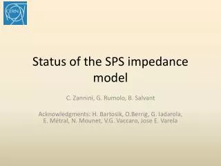
Update of the SPS transverse impedance model C. Zannini, G. Rumolo, B. Salvant Acknowledgments: H. Bartosik, O.Berrig, G. Iadarola, W. Hofle, E. Métral, N. Mounet, V.G. Vaccaro, Jose E. Varela
Overview • SPS transverse impedance model • Broadband impedance of step transitions • Future update of the model • Summary
SPS transverse impedance model • Elements included in the database: • Realistic model that takes into account the different SPS vacuum chambers weighted by the respective length and beta function. Also the iron in the magnets is taken into account Beam pipe
SPS transverse impedance model:wall impedance Horizontal SPS Wall impedance Horizontal driving and detuning are opposite in sign
SPS transverse impedance model: wall impedance Vertical SPS Wall impedance
SPS transverse impedance model • Elements included in the database: • Realistic model that takes into account the different SPS vacuum chambers weighted by the respective length and beta function. Also the iron in the magnets is taken into account • 19 kickers (CST 3D simulations) Beam pipe Kickers
SPS transverse impedance model:kicker impedance Horizontal SPS kicker impedance Peak due to the serigraphy
SPS transverse impedance model:kicker impedance Vertical SPS kicker impedance Peak due to the serigraphy
Evolution of the extraction kickers in the SPS 2014 8 8 Post-LS1
SPS transverse impedance model • Elements included in the database: • Realistic model that takes into account the different SPS vacuum chambers weighted by the respective length and beta function. Also the iron in the magnets is taken into account • 19 kickers (CST 3D simulations) • 106 BPHs (CST 3D simulations) • 96 BPVs (CST 3D simulations) BPV BPH Beam pipe Kickers
SPS transverse impedance model:BPMs impedance Horizontal SPS BPMs impedance Horizontal driving and detuning are about opposite in sign
SPS transverse impedance model:BPMs impedance Vertical SPS BPMs impedance Below 3% of the total SPS impedance
SPS transverse impedance model • Elements included in the database: • Realistic model that takes into account the different SPS vacuum chambers weighted by the respective length and beta function. Also the iron in the magnets is taken into account • 19 kickers (CST 3D simulations) • 106 BPHs (CST 3D simulations) • 96 BPVs (CST 3D simulations) • 200 MHz cavities without couplers (CST 3D simulations) • 800 MHz cavities without couplers (CST 3D simulations) • Enamel flanges (CST 3D simulations) Enamel flanges BPV BPH TW 200MHz and 800MHz Beam pipe Kickers
SPS transverse impedance model:cavities impedance Horizontal SPS cavities impedance
SPS transverse impedance model:cavities impedance Vertical SPS cavities impedance Below 3% of the total SPS impedance
Vertical coherent tune shift 20 % 40 % 60 % Measurements performed in September 2012 80 % 100 % Present SPS impedance model reproduces about 70% of the vertical tune measured in the Q20 Present impedance model reproduces the instability behavior (H. Bartosik, Talk at the SPSU, 12 December 2013)
Stability diagram: Q20 • Two regimes of instability in measurements • Fast instability threshold with linear dependence on εl • Slow instability for intermediate intensity and low εl • Excellent qualitative agreement with HEADTAIL simulations H. Bartosik measurements HEADTAIL simulations nominal Island of slow instability 4.5x10¹¹p/b @ 0.35 eVs LIU SPS-BD, 12. December 2013
Intra-bunch motion:Q20 H. Bartosik measurements HEADTAIL simulations Example for slow instability Example for fast TMC instability • Excellent agreement between measurements and simulation
Horizontal coherent tune shift Measurements performed in February 2013 The kicker impedance model predicts a slightly negative horizontal effective impedance (positive slope of the coherent tune shift) in agreement with the measurements
Overview • SPS transverse impedance model • Broadband impedance of step transitions • Future update of the model • Summary
Broadband impedance of a step transition • Based on the results of 3D EM simulations, the broadband impedance contribution due to an abrupt transition is independent of the relativistic beta. Therefore, based on the aperture model, the generalized broadband impedance of the PSB transitions has been calculated as: Transverse Impedance C. Zannini, Electromagnetic simulations of CERN accelerator components and experimental applications. PhD thesis, Lausanne, EPFL, 2013. CERN-THESIS-2013-076.
Pumping ports Impedance reduction campaign: shielding of the pumping ports, lepton cavities etc.) 2000 Total number of shielded pumping ports H. Burkhardt, G.Rumolo, F. Zimmermann: Measurements of SPS Single-Bunch coherent Tune Shifts and Head-Tail Growth Rates in the Year 2001 P. Collier et al.: Reducing the SPS Machine Impedance, 2002 The broadband impedance due to step transitions can give significant contribution to the coherent tune shift
Pumping ports Impedance reduction campaign: shielding of the pumping ports, lepton cavities etc.) 2000 SPS Pumping port SPS Pumping port shielding The picture does not include pumping holes
Broadband impedance of step transitions L Weak dependence on L
Broadband impedance of step transitions L2 Weak dependence on L2
Broadband impedance of step transitions The imaginary part of the transverse impedanceisweaklydependent on the cavitylengthbelow 1 GHz b = 17. 25 mm d = 78 mm For the main SPS cavitylike structures the first resonating mode iswellabove 1 GHz (r<80 mm) L2
Broadband impedance of step transitions Courtesy of Jose E. Varela
Vertical coherent tune shift 20 % 40 % 60 % 80 % 100 % Step transitions seem to explain almost the totality of the missing tune shift
Broadband impedance of step transitions:longitudinal plane L Weak dependence on L
Overview • SPS transverse impedance model • Broadband impedance of step transitions • Future update of the model • Summary
New elements to be added in the model • Simulations are ongoing or must be finalized • Septa • Wire scanner • Non standard elements (special transitions, valves) • Update due to future installations • New wire scanner • New kicker for high bandwidth feedback system • New MSI-V septum
New elements to be added in the model • Simulations are ongoing or must be finalized • Septa • Wire scanner • Non standard elements (special transitions, valves) • Update due to future installations • New wire scanner • New kicker for high bandwidth feedback system • New MSI-V septum
Longitudinal impedance Lt is the length of the cavity like structure Short length (below 0.1 m) of the cavity like structure would avoid narrow resonances below 2 GHz The impedance is strongly dependent on the cavity like structure length
Transverse impedance Impedance [Ohm/m] The impedance is strongly dependent on the cavity like structure length Impedance [Ohm/m]
Transverse impedance Impedance [Ohm/m] The effective vertical impedance for 10 stripline kicker modules is expected to be about 0.5% of the total SPS vertical impedance
Overview • SPS transverse impedance model • Broadband impedance of step transitions • Future update of the model • SPS Longitudinal impedance model • Summary
Summary and next steps • The SPS impedance model (kicker, wall, cavities, BPMs) explains about 70% of the measured vertical coherent tune shift • Transition pieces seem to be able to explain a large part of the remaining 30% • More realistic model of transition pieces • Update of the model including septa and wire scanner • Continuously update of the model according to new installations and modifications