Download
1 / 16
160 likes | 313 Views
M-B TRD Prototypes for the CBM Experiment in Test Beam and Simulation and First Results of Photon Measurement via Conversion. DGP Frühjahrstagung 11. März 2008 TU Darmstadt. Melanie Klein-Bösing Institut für Kernphysik WWU Münster. C ompressed B aryonic M atter Experiment. 2.

E N D
M-B TRD Prototypes for the CBM Experiment in Test Beam and Simulation and First Results of Photon Measurement via Conversion DGP Frühjahrstagung 11. März 2008 TU Darmstadt Melanie Klein-Bösing Institut für Kernphysik WWU Münster
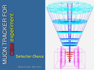
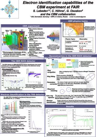
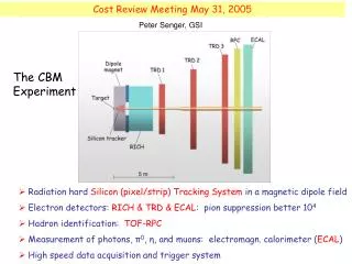
Compressed Baryonic MatterExperiment 2 > Physics > Exploration of the QCD phase diagram withollisions > Investigation of nuclear matter at highest baryon densities but still moderate temperatures in A+A collisions > Experimental task > Identification of hadrons and leptons in collisions at event rates of up to 10 MHz See also hk 31.3: “Exploring unknown territory of the nuclear phase diagram with CBM” (Joachim Stroth) > Electron ID > RICH+TRD+TOF > TRD: Tracking of all charged particles > Requirements for TRD > Pion suppression: ~100 > Position resolution: ~200-300 mm > At high rates (up to >100 kHz/cm²) and high multiplicities
MWPC-based Protoypes for TRD(M-B TRD) > MWPC-based prototypes (M-B TRD) Two individual MWPCs sharing one double-sided pad plane: ~twice the detection efficiency at same rate capability 3 Pads (5x10 mm2) a) View parallel to anode plane b) View perpendicular to anode plane
Test Beam in 2006 @ GSI p = 1.5 GeV/c HV = 1700 V Xe(85%)CO2(15%) 4 M-B TRD: Average Signal on Three Adjacent Pads • -> Only weak rate dependence (< 2%)
Position Resolution Residuals Residuals = difference between reconstructed and fitted value for y1-y2 5 Alignment y1, y2 = reconstructed hit positions in chambers 1 and 2 (M-B TRD) Position Resolution Position resolution = Width of residual distribution for a large number of tracks > Cuts chosen for constant efficiency -> good position resolution of < 200mm for rates up to 200 kHz/cm2 M. Klein-Bösing et al. NIM A585 (2008) 83-87
Charge Deposit of e and p double-sided prototype (M-B TRD) • e/pseparation • by Pb/Cherenkov 6 • > Single-sided vs. double-sided TRD geometry single-sided prototype (B TRD) • e • p • p=1.5 GeV/c • p=1.5 GeV/c > Better electron identification due to higher TR conversion probability • > e/p separation by • Pb/Cherenkov
Charge Deposit: Test Beam Data and Simulation > Good agreement of simulated and test beam data under assumption of 5% electron contamination 7 • > pions with 5% electron • contamination • > radiator parameters chosen • to fit the curves • e e: good agreement • p p: distributions don't fit
Pion Efficiency Likelihood to be identified as electron 8 -> Determination of pion efficiency and extrapolation for more detector layers • Pion misidentification probability • at 90% electron efficiency Limit at 90% electron efficiency • p • e -> Pion efficiency (= 1/pion suppression) in the desired region of 1/100 for 9 detector layers > Pion suppression significantly better than 100 for 9 TRD layers
Pion Efficiency Likelihood to be identified as electron 9 -> Determination of pion efficiency and extrapolation for more detector layers • Pion misidentification probability • at 90% electron efficiency Limit at 90% electron efficiency • p • e -> Pion efficiency (= 1/pion suppression) in the desired region of 1/100 for 9 detector layers > Pion suppression in a pure e and p beam can be even better
Application of Electron ID in CBMusing the M-B TRD geometry 10 • > Feasibility study of measuring direct photons via conversion: g Z→ e+e-Z • > Advantages • > Additional method to photon measurement by Ecal • > Also at low momenta: Good momentum resolution with tracking • > Tasks • > Vertex reconstruction of e+e- pairs • > Remove background to e+e- pairs from p0-Dalitz decays: p0→e+e- g • > Inclusive photon spectrum • > Largest contribution from p0 and h decays: • p0→gg(BR = 98.8%) h→gg(BR = 39.4%) • > Direct photons = ginclusive – g decay • > Measurement of enhancement compared to expected decay background
Electron Identification • > STS in a magnetic dipole field: • > Track reconstruction • > Momentum determination • > Prim. and sec. vertex reconstruction • > RICH+TRD+TOF: • > Electron ID (pion suppression > 104) 11 • > ID cuts@RICH • > Ring-track distance • > Ring radius • > NN cut against fake rings • > ... • > ID cuts@TRD • > Momentum ≥ 1.5 GeV/c • > Statistical analysis of energy loss spectra, • here: output of NN
Electron Efficiency and Pion Suppression 12 • > Central Au+Au collisions at 25AGeV beam energy (UrQMD)
Vertex Reconstruction of the e+e- Pairs 13 > e+e-: only secondaries, no combinatorial background • > Kalman-filter method: cut for „good vertices“: c2<3xNDF • > Most of reconstructed conversion vertices in the target • > Electron ID has vertex constraint • -> Use of conversions in the target (Zrec < 2 cm)
Reconstructed Opening Angle of the dileptons (q < 1°) 14 With Q cut: p0 Dalitz/all e+e-: 9.1% conversions/all e+e-: 68.3% Without Q cut: p0 Dalitz/all e+e-: 18.5% conversions/all e+e-: 80.2% > p0 Dalitz decays reduced by a factor of two > Elimination of wrongly reconstructed conversions at large Z positions > Increase the S/N: 4.3 -> 7.5
Inclusive Photon Spectrum 15 > Including 10photons/event > Photon uniformly distributed: • pT (0.,3.); Phi (0.,360.); Theta (2.5,25.); > Difference of spectra > Constant input spectrum recovered > Identification probability of photons via conversions (Z < 2cm)~2% > Theoretical conversion probability in ½ (250mu) gold target = 2.9%
Summary and Next Steps 16 > M-B TRD prototypes constructed and tested > Pion suppression factor is significantly better than 100 for 9 TRD layers [NIM A 579 (2007) 961-966] > Position resolution at high rates better than 200 mm [NIM A585 (2008) 83-87] > Simulated energy loss spectra agree with measured charge deposit > Next steps > Construction of real size prototypes -> perhaps beam test @ GSI in Sept. 08 • > First steps in photon identification via conversions • > Influence of vertex and opening angle cut on dileptons studied • > Input photon spectrum can be recovered • > Framework is ready for photon identification via conversions into e+e- • > Next steps • > Combinatorial background and p0 reconstruction • > Realistic photon input to simulation