Infrared Extraction Update
Infrared Extraction Update. L. Carr, D. Arena, A. Blednyk, S. Coburn, V. Ravindranath and NSLS-II Team NSLS-II EFAC Review 10-11 May 2007. Infrared Outline. NSLS-II Infrared beamlines and requirements: quick refresher Infrared Extraction: revised extraction geometry*

Infrared Extraction Update
E N D
Presentation Transcript
Infrared Extraction Update L. Carr, D. Arena, A. Blednyk, S. Coburn, V. Ravindranath and NSLS-II Team NSLS-II EFAC Review 10-11 May 2007
Infrared Outline • NSLS-II Infrared beamlines and requirements: quick refresher • Infrared Extraction: • revised extraction geometry* • large gap dipoles (excellent long-wavelength performance). • 1st mirror heat load* • Performance Figures • Beamline locations (brief)* • Environment (noise: vibration, EMI, etc.) • stability taskforce & workshop requirements • Top-off issues* • Bunch structure(s) for timing * addresses specific EFAC concerns and recommendations
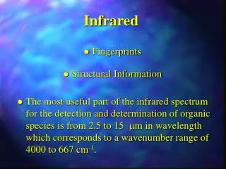
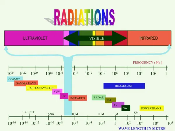
mid-IRstandard port far-IRlarge port Science and IR Source Requirements • Biological , Chemical, Environmental, Materials, Space … • 4000 cm-1 (l=2.5 mm) to < 400 cm-1 (l=25 mm) • mid and far-IR microprobe • mid-IR chemical imaging (raster scanning -> area imaging) • Imaging needs an extended source to optimally illuminate. • Materials (especially under extreme conditions) • Mostly “single point” spectroscopy • high pressures and temperatures • laser pump-probe • cryospectroscopy • high magnetic fields, spin resonance • 4000 cm-1 down to ~ 2 cm-1 (l=5 mm)
Mid-IR Extraction: Standard Dipole • Chamber with 24mm high interior • Plane 1st mirror, with slot • 14 mrad V (avg.) by 50 mrad H • small reduction in qV compared to internal toroidal mirror extraction • Collects dipole and 0° edge radiation • Other details to be determined: • required slot length to allow x-rays to pass • beam impedance • mechanical mirror mounting • mirror cooling (back or end surface)care to avoid sources of vibration Standard NSLS-II Dipole “conventional” extraction S. Coburn
FIR and mm-wave Extraction: Large Gap Dipole Chamber Large Gap Dipole • Chamber with 78mm high interior • Plane 1st mirror, with slot • 42 mrad V (avg) by 50 mrad H • small reduction in qV compared to internal toroidal mirror extraction, but less risk from waveguide cutoff effects (shorter distance) • Collects dipole and 0° edge radiation • Other details to be determined: • required slot length to allow x-rays to pass • beam impedance • mechanical mirror mounting • mirror cooling (back or end surface)care to avoid sources of vibration Have adopted largest of proposed dipole designs View into exit port S. Coburn Special chamber construction S. Coburn e
Mid-IR Brightness NSLS II VUV/IR
Far-IR Brightness cutoff effect due to chamber shielding lc ~ (h3/r)1/2
New extraction: Beam no longer at grazing incidence onto 1st collection/extraction mirror. Calculation with internal H2O cooling, no slot: Relative longitudinal error = 3 mm Relative transverse error = 8 mm Initial FEA Analysis of Surface Deformation 500ma, 3.6 GeV V. Ravindranath Conclusion: will need slot
Locations for IR Extraction • Standard dipole Mid-IR ports: • can be placed in proximity to related science activities (not constrained by accelerator symmetry requirements). • Large gap dipole Far-IR ports: • Large gap dipoles limited to 3 symmetric locations around ring. Both dipoles in a DBA cell, but typically only 2nd dipole available for IR extraction (due to ID upstream of 1st dipole). • Plan to locate 1 large-gap dipole cell-pair downstream of RF straight section (no ID, can use both dipoles for IR). Result: maximum of 4 far-IR extractions.(prefer downstream of RF, not injection) • Beamline floor plans: TBD “exaggerated” NSLS-II with 3 long straights, showing a symmetric arrangement of large-gap dipole pairs. candidate location for large gap dipole cell
IR Requirements for Stability Taskforce & Report Stability of electron beam through dipoles: • Specification request: • Position: 1 mm V, 3 mm H • Angle: 3 mrad V, 6 mrad H • Corresponds to 7% of beam size (compare to 10% overall NSLS-II specification). • Requirement defined to deliver: • minimum 300:1 S/N in worst-case-scenario • would be ~ 30X better than existing NSLS VUV/IR • frequency range up to 20 kHz. • Can benefit from even better stability (additional 30X will put noise near background for essentially all measurements).
NSLS II Infrared Capacity • In most cases, 2nd dipole of DBA cell is potential IR extraction location. • Slot in 1st mirror should allow for a downstream soft x-ray (BM) beamline. • 3-pole wiggler & IR edge extraction probably incompatible (both a 0° and angular pattern approaching 1/g). • Mid-IR: plan to develop beamlines 5 beamlines on 3 separate extractions: • H = 50 mrad & V ~ 14 mrad (avg.) • Special chambers required, but otherwise standard dipole (flexibility). • Single extraction port can serve 2 or 3 microprobe endstations. • Or entire 50 mrad horizontal can serve a single FPA imaging spectrometer • 3 ports => 1 split into 3 microprobes, 2 for FPAs = 5 beamlines. Can add more ports for growth. • Plan to locate in proximity to other Biological / Imaging beamlines (e.g. mXRF, mXANES). • Far-IR / THz / mm-waves: plan to develop 3 beamlines on 3 separate extractions (max = 4): • H = 50 mrad & V ~ 42 mrad (avg.) • Special chambers and special large-gap dipole magnets • Single endstation per extraction. • Locations constrained by 3-fold ring symmetry and RF straight
Top Off Issues • NSLS-II injection approximately once per minute: • expect some beam motion for ~ 1 second • IR spectrometer data collection “styles”: • long scan time, averaging many short (< 1 second) scans • raster scan imaging (~ 1 minute per point, but ~ 1000 points) • ultra-high resolution spectroscopy (> 5 minutes for single scan). • Software: • macros and VB scripts to monitor “beam available” signal, pause collections. (R. Smith: testing a script to see how 1 and 2 can be managed). • more work necessary for 3.
RF Buckets, Bunches and Timing • Infrared has been one of the key users of the storage ring bunch structure for time-resolved studies (methods dependent on bunches themselves). • no benefit from crab cavities, indirectly from laser slicing (CSR) • not limited to IR … all techniques where beam is not resolvable and fast detection not sufficient. • Issues: • Bunch lengths (sBL for NSLS II will be 10s of picoseconds) • Pulse Rep. Frequencies (PRFs) & synchronization to mode-locked lasers • 499.7 MHz RF, ring circumference = 792m, harmonic number = 1320 ( = 2x 2x 2x 3x 5x 11) • Mode-locked Ti:sapphire prefers 76 to 82 MHz, 75 to 100 MHz for Nd:YLF, more options with fiber lasers • note: 500MHz/6 -> PRF= 83.3 MHz • Jitter (bunches relative to RF, to each other) below 10% of bunch RMS, especially for frequencies > 1 kHz. • sets NSLS-II RF phase system stability requirements – stringent, but possible. • Harmonic cavity effects, de-tuned operations, low-a lattices: Still to be investigated.
Summary • Updated Infrared extraction • more conventional side-extraction, 1stplane mirror, with slot to allow x-rays through. • very large gap dipoles, unsurpassed far-IR performance for incoherent SR. • generally higher mid-IR brightness than existing NSLS VUV/IR, expect high stability too. • Capacity: • Plan to develop 3 extractions each (mid-IR & far-IR) during early phases of NSLS II operations. • corresponds to 8 beamline endstations, compare to existing 6 on NSLS VUV/IR • Potential for growth (especially mid-IR). • Stability: • Requirements to achieve S/N at least 30X better than NSLS VUV/IR. • More is better! • Pulse Repetition Frequencies (PRFs): • h=1320, booster at 1/5th for efficient filling of NSLS-II ring in top-off. • Needing more attention: detailed impact of top-off injection on various IR measurement methods.