Distributed Systems
Distributed Systems. Data Networking & Client-Server Communication Minqi Zhou mqzhou@sei.ecnu.edu.cn. Except as otherwise noted, the content of this presentation is licensed under the Creative Commons Attribution 2.5 License. Distributed systems.

Distributed Systems
E N D
Presentation Transcript
Distributed Systems Data Networking &Client-Server Communication Minqi Zhou mqzhou@sei.ecnu.edu.cn Except as otherwise noted, the content of this presentation is licensed under the Creative Commons Attribution 2.5 License.
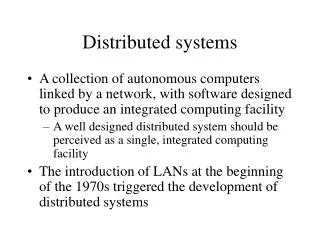
Distributed systems Independent machines work cooperatively without shared memory They have to talk somehow Interconnect is the network
Modes of connection Circuit-switched • dedicated path • guaranteed (fixed) bandwidth • [almost] constant latency Packet-switched • shared connection • data is broken into chunks called packets • each packet contains destination address • available bandwidth channel capacity • variable latency
What’s in the data? For effective communication • same language, same conventions For computers: • electrical encoding of data • where is the start of the packet? • which bits contain the length? • is there a checksum? where is it?how is it computed? • what is the format of an address? • byte ordering
Protocols These instructions and conventionsare known as protocols
Protocols Exist at different levels • understand format of address and how to compute checksum • request web page • humans vs. whalesdifferent wavelengths • French vs. Hungarian versus
Layering To ease software development and maximize flexibility: • Network protocols are generally organized in layers • Replace one layer without replacing surrounding layers • Higher-level software does not have to know how to format an Ethernet packet … or even know that Ethernet is being used
Layering Most popular model of guiding(not specifying) protocol layers is OSI reference model Adopted and created by ISO 7 layers of protocols
OSI Reference Model: Layer 1 Transmits and receives raw data to communication medium. Does not care about contents. voltage levels, speed, connectors Physical 1 Examples: RS-232, 10BaseT
OSI Reference Model: Layer 2 Detects and corrects errors. Organizes data into packets before passing it down. Sequences packets (if necessary). Accepts acknowledgements from receiver. Data Link 2 Physical 1 Examples: Ethernet MAC, PPP
OSI Reference Model: Layer 3 Relay and route information to destination. Manage journey of packets and figure out intermediate hops (if needed). Network 3 Data Link 2 Physical 1 Examples: IP, X.25
OSI Reference Model: Layer 4 Provides a consistent interface for end-to-end (application-to-application) communication. Manages flow control. Network interface is similar to a mailbox. Transport 4 Network 3 Data Link 2 Physical 1 Examples: TCP, UDP
OSI Reference Model: Layer 5 Services to coordinate dialogue and manage data exchange. Software implemented switch. Manage multiple logical connections. Keep track of who is talking: establish & end communications. Session 5 Transport 4 Network 3 Data Link 2 Physical 1 Examples: HTTP 1.1, SSL, NetBIOS
OSI Reference Model: Layer 6 Data representation Concerned with the meaning of data bits Convert between machine representations Presentation 6 Session 5 Transport 4 Network 3 Data Link 2 Physical 1 Examples: XDR, ASN.1, MIME, MIDI
OSI Reference Model: Layer 7 Collection of application-specific protocols Application 7 Presentation 6 Session 5 Transport 4 Network 3 Data Link 2 Examples: email (SMTP, POP, IMAP) file transfer (FTP) directory services (LDAP) Physical 1
Local Area Network (LAN) Communications network • small area (building, set of buildings) • same, sometimes shared, transmission medium • high data rate (often): 1 Mbps – 1 Gbps • Low latency • devices are peers • any device can initiate a data transfer with any other device Most elements on a LAN are workstations • endpoints on a LAN are called nodes
Connecting nodes to LANs network computer ?
Connecting nodes to LANs network computer Adapter • expansion slot (PCI, PC Card, USB dongle) • usually integrated onto main board Network adapters are referred to asNetwork Interface Cards(NICs) or adapters or Network Interface Component
Media Wires (or RF, IR) connecting together the devices that make up a LAN Twisted pair • Most common: • STP: shielded twisted pair • UTP: unshielded twisted pair (e.g. Telephone cable, Ethernet 10BaseT) Coaxial cable • Thin (similar to TV cable) • Thick (e.g., 10Base5, ThickNet) Fiber Wireless
Hubs, routers, bridges Hub • Device that acts as a central point for LAN cables • Take incoming data from one port & send to all other ports Switch • Moves data from input to output port. • Analyzes packet to determine destination port and makes a virtual connection between the ports. Concentratoror repeater • Regenerates data passing through it Bridge • Connects two LANs or two segments of a LAN • Connection at data link layer (layer 2) Router • Determines the next network point to which a packet should be forwarded • Connects different types of local and wide area networks at network layer (layer 3)
Networking Topology Bus Network
Networking Topology Tree Network
Networking Topology Star Network
Networking Topology Ring Network
Networking Topology Mesh Network
Transmission networks Baseband • All nodes share access to network media on an equal basis • Data uses entire bandwidth of media Broadband • Data takes segment of media by dividing media into channels (frequency bands)
Broadband: RF broadcasts http://www.ntia.doc.gov/osmhome/allochrt.pdf
audio +5.75 MHz video 6 MHz +1.25 MHz Broadband/Baseband: Cable TV Broadband 55-552 MHz: analog channels 2-78 553-865 MHz: digital channels 79-136 Baseband within Broadband DOCSIS: Data Over Cable Service Interface Specification (approved by ITU in 1998; DOCSIS 2.0 in 2001) Downstream: 50-750 MHz range, 6 MHz bandwidth - up to 38 Mbps - received by all modems Upstream: 5-42 MHz range - 30.72 Mbps (10 Mbps in DOCSIS 1.0, 1.1) - data delivered in timeslots (TDM) DOCSIS 3.0 features channel bonding for greater bandwidth
DOCSIS Modem tuner demodulator MAC cable modulator network interface CPU ethernet interface(to PC) Restrictions on upload/download rates set by transferring a configuration file to the modem via TFTP when it connects to the provider.
Baseband: Ethernet Standardized by IEEE as 802.3 standard Speeds: 100 Mbps - 1 Gbps typical today • Ethernet: 10 Mbps • Fast Ethernet: 100 Mbps • Gigabit Ethernet: 1 Gbps • 10 Gbps, 100 Gbps Network access method isCarrier Sense Multiple Access with Collision Detection(CSMA/CD) • Node first listens to network to see if busy • Send • Sense if collision occurred • Retransmit if collision
Ethernet media Bus topology (original design) • originally thick coax (max 500m): 10Base5 • then… thin coax (<200m): 10Base2 • BNC connector Star topology (central hub or switch) • 8 pit RJ-45 connector, UTP cable, 100 meters range • 10BaseT for 10 Mbps • 100BaseT for 100 Mbps • 1000BaseT for 1 Gbps • Cables • CAT-5: unshielded twisted pair • CAT-5e: designed for 1 Gbps • CAT-6: 23 gauge conductor + separator for handling crosstalk better
Wireless Ethernet media Wireless (star topology) • 802.11 (1-2 Mbps) • 802.11b (11 Mbps - 4-5 Mbps realized) • 802.11a (54 Mbps - 22-28 Mbps realized) • 802.11g (54 Mbps - 32 Mbps realized) • 802.11n (108 Mbps - 30-47 Mbps realized) ethernet Access Point
Connecting to the Internet • DOCSIS modem via cable TV service • DSL router • Ethernet converted to ATM data stream • Up to 20 Mbps up to ~ 2 km. • POTS limited to 300-3400 Hz • DSL operates > 3500 Hz • Modem • Data modulated over voice spectrum(300-3400 Hz) • Serial interface to endpoint • V.92: 48 kbps downstream, near 56 kbps up • Use PPP or SLIP to bridge IP protocol
Connecting to the Internet • Dedicated T1 or T3 line • T1 line: 1.544 Mbps(24 PCM TDMA speech lines @ 64 kbps) • T3 line: 44.736 Mbps (672 channels) • CSU/DSU at router presents serial interface • Channel Service Unit / Data Service Unit Phonenetwork LAN T1 line router CSU/DSU RS-232C, RS-449, V.xxserial line
Connecting to the Internet • Fiber to the Home, Fiber to the Curb • Ethernet interface • E.g., Verizon’s FiOS 30 Mbps to the home • Long Reach Ethernet (LRE) • Ethernet performance up to 5,000 feet • Wireless: • WiMax • EDGE (70-135 Kbps) • GPRS (<32 Kbps)
Clients and Servers • Send messages to applications • not just machines • Client must get data to the desired process • server process must get data back to client process • To offer a service, a server must get a transport address for a particular service • well-defined location
Transport provider Layer of software that accepts a network message and sends it to a remote machine Two categories: connection-oriented protocols connectionless protocols
Connection-oriented Protocols • establish connection • [negotiate protocol] • exchange data • terminate connection
Connection-oriented Protocols virtual circuit service • provides illusion of having a dedicated circuit • messages guaranteed to arrive in-order • application does not have to address each message vs. circuit-switched service analogous to phone call • establish connection • [negotiate protocol] • exchange data • terminate connection dial phone number [decide on a language] speak hang up
Connectionless Protocols • - no call setup • - send/receive data • (each packet addressed) • - no termination
Connectionless Protocols datagram service • client is not positive whether message arrived at destination • no state has to be maintained at client or server • cheaper but less reliable than virtual circuit service analogous to mailbox • - no call setup • - send/receive data • (each packet addressed) • - no termination • drop letter in mailbox • (each letter addressed)
Ethernet • Layers 1 & 2 of OSI model • Physical (1) • Cables: 10Base-T, 100Base-T, 1000Base-T, etc. • Data Link (2) • Ethernet bridging • Data frame parsing • Data frame transmission • Error detection • Unreliable, connectionless communication
Ethernet dest addr src addr frame type data (payload) CRC 6 bytes 6 bytes 2 46-1500 bytes 4 18 bytes + data • 48-byte ethernet address • Variable-length packet • 1518-byte MTU • 18-byte header, 1500 bytes data • Jumbo packets for Gigabit ethernet • 9000-byte MTU
IP – Internet Protocol Born in 1969 as a research network of 4 machines Funded by DoD’s ARPA Goal: build an efficient fault-tolerant network that could connect heterogeneous machines and link separately connected networks.
Internet Protocol Connectionless protocol designed to handle the interconnection of a large number of local and wide-area networks that comprise the internet IP can route from one physical network to another
IP Addressing Each machine on an IP network is assigned a unique 32-bit number for each network interface: • IP address, not machine address A machine connected to several physical networks will have several IP addresses • One for each network
IP Address space 32-bit addresses >4 billion addresses! • Routers would need a table of 4 billion entries • Design routing tables so one entry can match multiple addresses • hierarchy: addresses physically close will share a common prefix
IP Addressing: networks & hosts • first 16 bits identify Rutgers • external routers need only one entry • route 128.6.*.* to Rutgers cs.rutgers.edu 128.6.4.2 80 06 04 02 remus.rutgers.edu 128.6.13.3 80 06 0D 03 network # host #