Download
1 / 87
900 likes | 1.04k Views
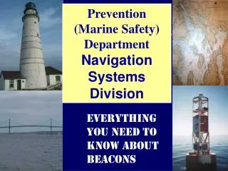
Navigation Systems Division. Everything you need to know about Beacons and Daybeacons. Beacons. Training Objectives. Identification of various structures. Proper use and maintenance of retro-reflective material. Structures.

E N D
Navigation SystemsDivision Everything you need to know about Beacons and Daybeacons.
Training Objectives Identification of various structures. Proper use and maintenance of retro-reflective material.
Structures • Support visual and audible navigation equipment in a fixed location at a designed elevation that establishes the geographic range of the Aid to Navigation. • Two Classifications: • Lighthouse • Beacon
Lighthouse • Enclosed edifice that houses protects, displays, or supports visual, audible, or radio aids to navigation. • Can be manned or unmanned. • Located in an offshore, wave swept, exposed environment. • Or as a landfall object.
Beacon • A support platform for visual and/or audible aids to navigation. • Simple in design. • Constructed of wood, concrete or steel. • May be lighted or unlighted.
Design Considerations • Payload requirements: • Dead load (batteries and equipment) • Live load (servicing personnel) • Environmental factors: • Weather (wind, waves, storms) • Site location (water depth, type of bottom) • Collision (high destruction areas, ice)
Operational Requirements • Height • Size
Operational Requirements • Contrast • Vegetation • Background lights
Construction Methods • WLICs Driven with diesel hammer • ANTs Jetting • Contract
Structure Categories Single pile Multiple pile
2 Single Pile Structure • Used in protected or semi-exposed locations where fixity can be attained.
Multiple Pile Structures • Used whenfixity can not be achieved with single pile. • Two categories: • Dolphin • Platform Structure
1 Dolphin • Battered pile Three to seven piles driven at an angle with the bottoms spread and the tops secured with wire rope or bolts and shear connectors.
Dolphin • Cluster pile • Three or more piles driven vertically with their surfaces in contact with each other and wrapped tightly at various heights.
Platform Structure • Three or more separate piles driven vertically, connected at the top by a platform that spreads the load over all the piles. Usually is the foundation for skeleton towers.
Materials Used • Wood • Economical, if life expectancy is greater than 6 months wood must be treated. • Steel • Expensive, strong, can be driven into hard bottoms, must be driven to required height. • Concrete • Expensive, fragile, must be driven to required height.
Towers Two types of towers: Guyed skeleton Supports equipment on land less than 30’. Free standing skeleton Supports equipment on land or marine sites when over 30’.
Guyed Skeleton • Commonly called a “TV tower.” • Triangular in shape. • Galvanized 1 1/4” steel pipe and 3/16” guide wires. • Each section is 10 ft. in height. • Usually not built over 30 ft.
Free Standing Skeleton Tower • Commonly called “5 ft pipe towers”. • Constructed of galvanized metal. • Can be uniform or tapered. • Usually, not built over 100 ft. in height.
Related Equipment Ladders • Most often metal. • Wood can only be used only for special circumstances and must meet minimum requirements. • 2x4s nailed to the pile does not meet the requirements.
Safety Belt / Harness • According to the office of safety: • The use of a safety harness in lieu of a safety belt is recommended, but not mandatory. • The requirement to use these devices remains at 20’, as currently published.
Safety Climbing Device • Will be installed on all structures over 20 ft. • It looks like a pipe with teeth and is installed on the ladder rungs.
A safety climb car is attached to the climbers safety belt and is slid over the safety climb rail.
As the climber leans back the safety climb releases allowing ascent
If the climber slips the safety climb catches preventing a fall
Battery Box • Large box is designed to hold up to 4 secondary batteries. • Small box is designed to hold up to 2 secondary batteries. • Single battery boxes are available commercially and are acceptable as long as they are white in color.
CHANNEL Radar Reflector • Installed when the reflectivity of the structure doesn’t meet the operational requirements. • A standard radar set should detect it at 1.5 to 2 NM when mounted 10 ft above the water. • Must be properly oriented to the channel.
Dayboards • A dayboard shall always be installed for maximum utility. • The dayboard should be the dominant component of the silhouette with the battery box hidden behind it.
Mounting Dayboards • Dayboards should be fastened so the dayboard becomes sacrificial in high winds. • Dayboards shall be fastened to meet or exceed a lifetime of 5 years. • The fasteners shall not pierce the retro-reflective boarder or characters.
o 5 Mounting Dayboard may be installed approximately 5 degrees from vertical.
o 3 0 CHANNEL Mounting • Whenever possible, dayboards shall be mounted on an angle to the channel. • The angle will vary to best suit the channel. • For a straight channel about 30 degrees. • This makes the number easier to read when abeam.
Dayboards • Dayboards differ in size and shape depending on the marking system and the specific function. • Each dayboard has a designator composed of a number followed by a group of letters.
3’ 4’ Dayboards • A number gives the width of the dayboard in feet.
S-Square T-Triangle J-Junction M-Mid-Channel K-Range N-No Lateral Significance Dayboards • The first letter refers to the shape or purpose of the dayboard.
R- Red G- Green W- White B- Black Dayboards • The second letter represents the key color.
R- Fluorescent red G- Fluorescent green W- White B- Black Dayboards • The third letter indicates the color of stripe (range dayboards only).
Dayboards • Additional information is shown by letters placed after a dash (-) • I - Intracoastal • SY - yellow square • TY - yellow triangle
6’ Dayboards 6KRW-I
4’ Dayboards 4JR-SY
Nominal Range • As a mariner approaches a dayboard from a distance it is first detected as an object apart from its surroundings. This is the detection range
Nominal Range • Upon coming closer to the dayboard it can be recognized as an aid to navigation. This is the recognition range
Nominal Range • Finally the aid can be identified when the mariner is close enough to read the numbers and letters. This is the identification range
3SG and 4TR • nominal range 1NM • 4SG and 6TR • nominal range 2NM • 6SG and 8TR • nominal range 3NM Nominal Range • The nominal range rating is used to classify dayboards
Preparation • The technical manual provides cutting patterns for dayboard backings. • Acceptable materials are 3/8” or 1/2” plywood or 1/8” aluminum sheet. • The surface of the dayboard is covered with a colored vinyl film and retroreflective tape boarder.
Retroreflective tape Vinyl Film Films