Download
1 / 47
470 likes | 641 Views
CALICE, a frame for R&D on calorimetry. Where do we stand today?. Current developments in the CALICE collaboration, the objectives. The R&D effort. The CALICE collaboration. ECAL + HCAL DESY proposal. The aim. Prove the existence of a calorimeter design hardware and software

E N D
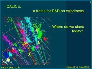
CALICE, a frame for R&D on calorimetry Where do we stand today?
Current developments in the CALICE collaboration, the objectives The R&D effort The CALICE collaboration ECAL + HCAL DESY proposal The aim Prove the existence of a calorimeter design hardware and software fulfilling the requirements for a linear collider experiment through specific technological developments up to a physics prototype of the complete calorimeter Be ready to build the calorimeter
S.Chekanov, G.Drake, S.Kuhlmann, S.R.Magill, B.Musgrave, J.Proudfoot, J.Repond, R.Stanek, R.Yoshida Argonne National Laboratory D.R.Ward, M.A.Thomson The Cavendish Laboratory, Cambridge University S.Valkar, J.Zacek Charles University - Prague P.D.Dauncey Department of Physics,Imperial College London H.Araujo, J.M.Butterworth, D.J.Miller, M.Postranecky , M.Warren Department of Physics and Astronomy,University College London R.J.Barlow, I.P.Duerdoth,N.M.Malden , R.J.Thompson The Department of Physics and Astronomy, The University of Manchester S. Abraham, V.Djordjadze, V. Korbel, S.Reiche, P.Steffen DESY - Hamburg V. Ammosov, Yu.Arestov, B.Chuiko, V.Ermolaev,V.Gapienko, A.Gerasimov, V.Koreshev, V.Lishin, V.Medvedev, A.Semak, V.Shelekhov, Yu.Sviridov, E.Usenko, V.Zaets, A.Zakharov Institute of High Energy Physics - Protvino J.Cvach, M.Janata, M.Lokajicek, S.Nemecek, J.Popule, M.Tomasek, P.Sicho, V.Vrba, J.Weichert Institute of Physics, Academy of Sciences of the Czech Republic - Prague M.Danilov, Y.Gilitski, V.Kochetkov, I.Matchikhilian, V.Morgunov, S.Shuvalov Institute of Theoretical and Experimental Physics - Moscow B.Bouquet, G. Martin, J-P. Richer, Z.Zhang Laboratoire de l'Acc₫l₫rateur Lin₫aire - Orsay
F.Badaud, G.Bohner, F.Chandez, P.Gay, J. Lecoq, S.Monteil Laboratoire de Physique Corpusculaire - Clermont E.Devitsin, V.Kozlov, L.Popov, S.Potashov, A.Terkulov Lebedev Physics Institute - Moscow J-C.Brient, A.Busata, A.Karar, P.Mora de Freitas, G.Morinaud, D.Orlando,H.Videau LLR - Ecole Polytechnique - Palaiseau A. Savoy-Navarro LPNHE - Universit₫ Paris6/7 S.Apin, I.Bagdasarova, V.Galkine,E.Gushin, A.Kaoucher, V. Saveliev, K.Smirnov, M.Zaboudko Moscow Engineering and Physics Institute P.Ermolov, D.Karmanov, M.Merkin, A.Savin, A.Voronin, V.Volkov Moscow State University P.Roca Physique des Interfaces et Couches Minces - Ecole Polytechnique - Palaiseau Ilgoo Kim, Taeyun Lee, Jaehong Park, Jinho Sung School of Electric Engineering and Computing Science, Seoul National University, Korea C.M.Hawkes, S.J.Hillier, R.J.Staley, N.K.Watson School of Physics and Astronomy, University of Birmingham A.Brandin, A.Ridiger State Research Center "INTERPHYSIKA" , Moscow M.Ashurov, I.Rustamov, E.Gasanov, K.Khatamov, S.Ismoilov Tashkent University + NI
The elements of the study (up to now) A Si-W electromagnetic calorimeter Two versions of hadronic calorimeter with scintillator tiles read analogically with RPC (or other detector) read digitally An adequate reconstruction software based on analytic energy flow A prototype to be put in a beam in 2004
The Si- W electromagnetic calorimeter Current developments in the CALICE collaboration, the objectives The main design problems Area of silicon, its price Wafer design to reduce dead space The number of channels, the space Getting the signals out, coherent noise Making the mechanical structure What about dead zones Behaviour of hadrons
This is a cost prediction for microstrips! DATA From H.F-W. Sadrozinski, UC-Santa Cruz Moore's Law for Silicon Detectors 50 4'' Wafer size 6'' Number of masks Yield (good tolerance to dead channels) Þ cost/area ($/cm²) 10 Used in the TDR << 2 $/cm ² TDR 96/130 ME 2 2 $/cm² Blank wafer price 6'' 1
from JC Brient St- Malo Re-calculate the estimation of cost, using the2 €/cm²for the silicon ¥The cost of the ECAL is between 68 (20 layers) to99(40layers) M€ ¥With the HCAL (i.e. version DHCAL) , the total cost of the calorimeter ranges from 129(20 layers) to175(40 layers) MCH (CMS equivalent is 145 MCH) 1 -For the complete set ECAL + HCAL + Muon-CH ( MCH) 2 -The change of the geometry can further reduce the cost (length of barrel, internal radius,...) 18/40% reduction CMS 216 Calice -FLC 132/178
Vaclav Vrba Wafers for the physics prototype One guardring per wafer AC coupling through resistor and capacitance made by deposition of amorphous silicon Gluing
Getting the signals out, where to put the FE electronics? TDR on the side of modules: (accessible), easy to cool number of lines, connections inside the calorimeter: more accessible?? easy to connect cooling? New study
A design with electronics inside detector AC coupling elements? Thermal contact Aluminium 1.3 mm Cooling tube Cooling tube VFE chip powerline command line signal out 1.0 mm PCB Pad 0.5 mm Silicon wafer Gluing for electrical contact
Current design of prototypes Thermal study Pick up study Front- end study (Opera) } for prototype for final design Detector slab study Mechanical structure study Structure Physics prototype Wafers
1st structure (1.4mm of W plates) 2nd structure (2×1.4mm of W plates) 3rd structure (3×1.4mm of W plates) HCAL structure VME ECAL Electronics 370 mm 370 mm BEAM 180 mm Beam monitoring Detector slab Movable table Silicon wafer Movable table Physics Prototype – global presentation from Marc Anduze, LLR CALICE Collaboration
Progress report on the prototype from JC Brient St- Malo Mid-march ¥ A first sample of tungsten plates arrives at LLR => metrology ¥The design of the front-end chip is fixed. First batch for test. End-march ¥ Production of the final set of masks for the silicon wafers processing Beginning-April ¥ Start the production of a sample of 40 tungsten plates corresponding to the first technological test and first stack of prototype April-May ¥ Processing of the first 25 silicon wafers (DC coupled) May-September ¥ Processing and test of about 100 silicon wafers ¥ Final submission of the VFE chip for the prototype
The hadron calorimeter, tile version Slides by Volker Korbel
Scintillator light yield Scintillator : uniformity of RO New Scintillators: ~6600 m2, costs! Reflector foil: mirror or diffraction, light yield Reflector foil: uniformity of RO • Tile-WLS system: • optimal coupling, • light yield, • uniformity • >>>> 5x5 cm2, than: ...7x7....16x16cm2 tiles Green WLS fibre: attenuation length WLS fibre: bending in small radius WLS fibre: ageing, rad. hardness WLS fibre: fibre end mirroring clear RO fibre: attenuation length Optimisation studies on the tile-WLS fibre system at DESY, ITEP and LPI/Moscow and Prague. V.Korbel, DESY, 24.6.2002
s-Loops with PM :ph.e./tile ph./cell • 1 ~10 240 • 2 ~15 360 • 3 ~16 384 • unbent fibres: • along edge, no groove: 7.0 168 • along groove in centre 7.7 184 • diagonal fibre, groove: 10.5 256 • diagonal, minimal bend: 11.0 264 • Criteria to use unbent, straight fibres: • easy to insert, • less risk of damage, • no bending stress, • > less ageing expected !!! Remark: these numbers are expected to be improved further by ~ 30-40% TESLA Tile-HCAL, Best coupling shape for WLS fibres? V.Korbel, DESY, 24.6.2002
Photodetectors for the Tile-HCAL • Inside 4T magnetic field: • HPDs, expensive ?? • APDs, arrays possible, to study • Si-photomultipliers (Si-PMs) • APDs, Study at DESY and Prague • 4x8 channel Si-APD array, Hamamatsu S8550, • 1,6x1,6 mm2 pixels >> 3x3mm2 • low capacities 10-15 pF possible, >> low amplifier noise • at 360-380 V gain of 100-300 possible, but excess noise? • temperature stability, gain shift of 1-2% /°C, overcome by monitoring • >> work on integration with monolithic preamps (OPERA-type) • Si-PMs, Study at MEPHI/Moscow • silicon photodiodes with Geiger mode amplification, • pixels of 20 mm diameter, 103 pixels/mm2, dynamic range? • ~30 V operation voltage, large gain of ~105 -106 • Q.E ~ 20% at 500nm, • individual detectors only, ~1.5x1.5 mm2 active area • see: • E. Lorenz, Evaluation of the new S8550 APD array... and • Boris Dolgoshein, Silicon Photomultiplier and ist Applications, • in 3. Beaune Conf. On New Developments in Photoproduction, June 2002 V.Korbel, DESY, 24.6.2002
Tile-HCAL minical-array • Assembled with up to • 27 scintillator layers: • 165 scintillator tiles of: • 5x5 cm2 >> 45 cells • 10x10 cm2 >> 8 cells • 20x20 cm2 >> 2 cells • read out by • ~ 50 cm WLS fibres to • photo-detectors: • 16 small PMs • 3x16 MA-PMs, • later (August): • 1x32 M-APD array (Prague) • Si-PMs (MEPHI, Moscow) Track chambers? Cell structure Stack and Tile structure Aim of this device is study of: light yield, stability, ageing and calibration with MIPs V.Korbel, DESY, 24.6.2002
The hadron calorimeter, the digital version information from DHCAL subcollaboration: IHEP, Interphysica, LLR, MEPhI, Seoul U. RPC's
by courtesy of Vladimir Ammossov 1x1 cm2 Pads outside Gap 1.2 mm Glass plates 1 mm TFE/N2/IB 80/10/10 Pads inside Efficiency to mip > 98% Signal on 50 W : 3 V
Thin PCB (1mm) combining pads and circuitry Scheme for a digital HCAL signal detection Thin packaging, TQFP 1 mm Power dissipation ~ 1 mW/ch Fe or .. Pad Chip insulating layer PCB resistive layer Glass Spacers conductive layer Fe insulating layer
Read out scheme for a 64 channel chip ~ 64 million channels Cost < 0.2 Euros/ch Reading the chips through a token ring
Currently designing the RPC - FPGA interface Current to voltage conversion Pulse stretching Digital output (CMOS compatible) Low input impedance Overvoltage protection of FPGA Low power consumption through current mirrors
The impact of using gas detectors read digitally up to recently the simulation for the digital solution was done with scintillator cells. we moved to simulate RPC's and that's different!
by courtesy of Anatoli Sokolov Not only it is digital but it could seem almost compensating! Almost a factor 3 between gas and scintillator Investigating...
by courtesy of Anatoli Sokolov The sigma was estimated through a gaussian fit
The sigma is estimated by quartiles: take out 16% on the left on the right No difference for hadrons between scint. and gas NN seems to bring in both cases a 1.5 improvement
Note http://polype.in2p3.fr/geant4/tesla/www/index.html#dgdl The software side Simulate more realistically RPC's, other detectors (MOKKA) Reconstruct photons, charged tracks, neutral hadrons Identify leptons Performances Recent release of Simdet v4 Writing of a geometry tool kit based on Geant4 but reachable from different languages Rules Persistency: interface Study of a "human level" language for geometry description
Iron Glasses G10 Gas Chamber Iron Spacers Magnetic field direction What's new I: RPCs in HCAL
Reconstruction Performances Identification
Simulation from MOKKA, an application of Geant4 Seeing a W dijet impact on the first 4 X0 of the calorimeter in q f projection The square is 100 mrad wide X generated g's 8 + charged 4 * neutral had. 1 O reconstructed g's
Some results at 800 GeV on photons number of reconstructed g's versus number of generated g's Photon reconstructed energy versus true energy Results from REPLIC GeV
Distribution of event photonic true multiplicity and reconstructed Distribution of event photonic true energy and reconstructed
Energy distribution for true photons and reconstructed ones including fakes GeV
Energy distribution of generated true photons and reconstructed true photons A reconstructed photon is associated to a true one if more than 75% of its energy comes from it. GeV
Difference between the true photon energy and the reconstructed one per event. The fit is done with 2 gaussians. Norm1 101.88 Mean1 0.23 GeV s1 7.01 GeV Norm2 35.84 Mean2 - 0.02 GeV s2 18.49 GeV c2/dof = 1.1 GeV
Photon reconstruction efficiency at low energy GeV
Pattern recognition from mip identification and vertexing P. Gay St-Malo same for neutrons and K0 .145/ÖE + .02
Impact of the Neutral Hadrons Neutral hadron reconstructed replaced by MC truth ? From P. Gay energy flow session St- Malo
Few new results on particle identification in jets Using the same technique as the ALEPH tau analysis (HLM) MUONS (without using muon chambers) ------- 2<P<5 P>5 =========================== Eff. mu-> mu 24/31 54/54 Eff. PI -> mu 46/4698 56/3064 ELECTRONS (using dE/dx values and errors from SIMDET v4) ---------- 1<P<1.5 P>1.5 Eff. el-> el 20/21 117/118 Eff. pi-> el 7/2492 0/9472 JC. Brient
Conclusion poursuivons le combat la lotta continua keep working
by courtesy of Anatoli Sokolov The sigma is estimated by quartiles: take out 16% on the left on the right No difference for hadrons between scint. and gas NN seems to bring in both cases a 1.5 improvement