Download
1 / 14
160 likes | 360 Views
1 u. 1 u. EXH. 2 u. PULLING. 10 u. Intensifier Principles of Operation. Use left click or right arrow to advance slides. Boyle’s Law for gasses:. “ His law gives the relationship between pressure and volume if temperature and amount are held constant”

E N D
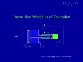
1 u 1 u EXH 2 u PULLING 10 u Intensifier Principles of Operation Use left click or right arrow to advance slides
Boyle’s Law for gasses: “His law gives the relationship between pressure and volume if temperature and amount are held constant” If the volume of a container is increased, the pressure decreases If the pressure in a container is decreased, the volume increases Pressure x Volume = Constant P1V1 = P2V2
Consider two chambers, housing two pistons, connected by a shaft. Since the stroke of the piston in both chambers is equal, Boyles Law states that the ratio of Pressure to Area in both chambers is equal P1A1 P2A2 If the pressure on the left (P1) is 80 psi and the area is 10 in2, the resulting pressure in the right chamber will depend on the area (A2). If A2 is 1 in2, than P2 will be 800 psi
1 u 1 u 2 u 1 u 10 u CVS1 PUSHING EXH 1 u 1 u EXH 2 u PULLING 10 u Double Acting Principle Pushing Air at 100 psi enters the left air cylinder chamber (air piston area = 10 in2) pushing it to the right. The hydraulic piston is 2.0 in2 and the rod is 1.0 in2. Since the crossover check valve allows oil to flow into the rod chamber, the effective area pushing is the rod area, yielding a 10:1 air to hydraulic ratio. Pulling Air at 100 psi enters the right air cylinder chamber pushing it to the left (pulling the hydraulic piston). The “pull” ratio is also 10:1 as determined by the differential area in the hydraulic piston and rod. Note also during this stroke, oil is being drawn into the piston end for the next “push” stroke.
Click Next Slide for a Demonstration Of the Double Acting Principle Oil Pressure Out Air Pressure In Tank Exhaust
Oil Pressure Out Air Pressure In Tank Exhaust
Oil Pressure Out Air Pressure In Tank Exhaust
Oil Pressure Out Air Pressure In Tank Exhaust
Oil Pressure Out Air Pressure In Tank Exhaust
Oil Pressure Out Exhaust Tank Air Pressure In
Oil Pressure Out Exhaust Tank Air Pressure In
Oil Pressure Out Exhaust Tank Air Pressure In
Click next slide to view summary… Oil Pressure Out Exhaust Tank Air Pressure In
Summary ofPrinciples • Fluid pressure in times the ratio equals maximum fluid pressure out in a stalled condition • The ratio of areas determines the output pressure • The same principle (Boyle’s Law) appliesfor all pump products including the Vac-Pak • The larger the ratio, the less flow that will be achieved Click next slide to start over…