Download
1 / 18
180 likes | 302 Views
CLIC accelerating structures: study of the tolerances and short range wakefield considerations. R. Zennaro CERN. RF Design optimization. I b. B T. Bunch population. Long range wake. Bunch separation. Design optimization loop. Luminosity. I b /B T. Short range wake. K. Bane.

E N D
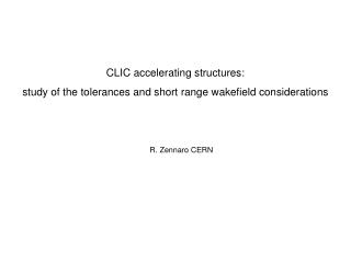
CLIC accelerating structures: study of the tolerances and short range wakefield considerations R. Zennaro CERN
RF Design optimization Ib BT Bunch population Long range wake Bunch separation Design optimization loop Luminosity Ib/BT Short range wake K. Bane Structure design (efficiency, gradient, etc..) Tolerance study Feasibility , selection of the technology Disk Quadrant
p g a Karl Bane short range wake for periodic geometric Longitudinal wake function Transverse wake function
Range of validity CLIC region K.B. range of validity • The validity of K.B. formulas has been investigated in the full CLIC region by using the 2D code ABCI: • Good results for the longitudinal wake • Some discrepancies for the transverse wake for small a/p
Dependence on a Dependence on g Fitting (tentative) Fitting (S0) Very good fitting with two free parameters fitting (b, S0) Poor fitting with a single free parameter (S0) but in the full range Next: tentative of fitting on a smaller range limited to X band
Non-periodic structures: longitudinal wake Example:0.335 < a/p < 0.603; 28 cells K.B. provides good results also for terminated tapered structures
K.B. is valid for rectangular irises but the reality is different… Let’s consider the combination of different wakes originated by different geometries Rounded irises In this case a=2mm is the minimum distance to the axis The result is not bad for longitudinal wake… The rounding of the irises seems to be the main approximation of K.B. formulas …and better for transverse wake
B D A P Phase slip: systematic errors loaded unloaded Integrated gradient -5.1% Integrated gradient -4.7% BD goal: 2%...the tolerance for the diameter (2B) should be 1 micron or better
Phase slip: random errors Vector of the structure Vector of the errors Most critical distribution Results: Most critical distribution: average phase slip: 11.7 degrees 1 micron (DB) systematic error: 10.7 degrees
Matching of the cells and standing wave components (no phase slip) A tolerance of 1 micron in the diameter (2*B) origins a VSWR~ 1.03; largely good enough for BD and acceptable for BDR considerations
Δz1 Δz1≈ D/a* Δz Bookshelf or longitudinal misalignment of half-structure Structure in quadrants problem mainly for the machining and assembly Dz Structure in disks problem mainly for the brazing (assembly); probably easier to achieve
Bookshelf or longitudinal misalignment of half-structure Direct kick calculation Panofsky Wenzel (cross-check) Equivalent bookshelf angle: α=dz/2a DVx/DVz~0.087*Dz computed Middle cell of CLIC_G (a=2.75mm) DVx/DVz=Dz/(4*a)=0.09*Dz Prediction Tolerances: 1micron or 180 μrad (achievable)
Thermal isotropic expansion Assumption: isotropic dilatation for small variation of the temperature of the cooling water Conservative approach: same T variation for the full linac (present design; one inlet for one linac) • Dilatation has two effects on phase: • Elongation of the structure; 1D problem, negligible effect • Detuning and consequent phase error of each cell; 3D problem, dominant effect requirement The average gradient variation is “equivalent” to 0.2 deg phase jitter(*) (drive beam-main beam phase) (*) In the case of synchronous phase = 8 deg
SA: iris shape accuracy OD: outer diameter ID: inner diameter Th: iris thickness Ra: roughness TD18_disk Specified Achieved Structure production: what we have achieved (courtesy of S. Atieh) Metrology results of two structures manufactured by the same company with the equivalent RF design. Two different technologies: disks and quadrants TD18_quadrant 16
Assembly test for structures in quadrants: elasting averaging (courtesy of J. Huopana) Principle is to use multiple contacts and elasticity of the material to decrease the effects of manufacturing errors in assembly Test pieces outside tolerances, initial plastic deformation but decent repeatability
Conclusions • K.B. functions are extremely useful tools for 2D periodic structures • K.B. range of validity is larger than predicted but not enough to cover CLIC region • A fitting with only one free parameter is under investigation • K.B. does not consider rounded irises, a possible correction is proposed • K.B. can be used with good results also for non-periodic structures • Diameter of the cells (2*B) is the most critical tolerance (1 micron or better) due to phase slip • For this tolerance the VSWR does not represent a problem • Bookshelf tolerances can be satisfied by structure in disks; it is critical for structures in quadrants • Cooling water temperature could require a stabilization @ 0.1 C • Disk technology (milling) is ready, quadrant is not (machining & assembly)