Download
1 / 26
260 likes | 530 Views
MMT Encoder Upgrade. D. Clark February 2010. Motivation. Recent elevation tape encoder failure with scratches and marks Failure of elevation absolute encoder resolver (coarse part of 25-bit value) Costs to upgrade encoder very nearly equal to replacement of existing tapes on elevation

E N D
MMT Encoder Upgrade D. Clark February 2010
Motivation • Recent elevation tape encoder failure with scratches and marks • Failure of elevation absolute encoder resolver (coarse part of 25-bit value) • Costs to upgrade encoder very nearly equal to replacement of existing tapes on elevation • Ongoing azimuth servo upgrades open opportunity for main-axis upgrade effort
Problems with Absolute Encoders • 512- and 1024-cycle/rev error terms in Inductosyn • Null error at cardinal angles of resolver and Inductosyn electrical cycle • Low-frequency spatial error from resolver outputs • Complex analog signal-processing hardware produce error terms, some of which are subject to aging and drift • 25-bit resolution lower than tapes OR absolute encoder offerings • Velocity estimation noise considerably higher compared to using tapes or RCN829 • IP-Digital48 is end-of-life and not easily replaceable • Internal encoder parts are extremely difficult to repair or replace as the recent resolver failure shows
Proposed New Encoder Heidenhain RCN829 Guaranteed ±1” accuracy 29-bit resolution 414 counts/arcsecond 32768-line incremental channel EnDat 2.2 interface
Considerations for Encoder Replacement • Mechanical – Can the RCN829 be mounted to achieve full accuracy? • Electrical – Can the RCN829 be cabled and powered for correct operation? • Environmental – Does it work at 2.5km altitude over -10 to 30C, and is it ozone-resistant? • Integration – Can the RCN829 and associated IK220 readout board be used in the existing mount control system software? • Performance – What performance in pointing and tracking can be expected, and is it sufficiently higher than the existing system to justify it? • Cost – How does the cost compare to replacing the tape encoders or improving the performance (e.g. RON905 stack) of the existing encoder system? • Time – What is the lead time? How long to complete the replacement? • Staffing – How many people and how much effort will be needed?
RCN829 Mechanical Mounting Overview Major mounting tolerances: Radial runout – 0.02mm Axial runout – 0.02mm? Mounting shoulder – 0.1mm w.r.t shaft centerline 50% overhead on catalog starting torque (2.25Nm) implies 3.84e9N/rad stiffness on coupling shaft to stay below 1 encoder count of error – using steel (77GPa), a 100mm x 50mm shaft has torsion ≈ 61mas…windup must be taken into consideration in control design Avoid flexible coupling if possible! Permanently blocks Nasmyth feed. Do we care?
Front-mounting arrangement Rear-mounting arrangement Mounting dimensions for 100mm dia. shaft RCN829 unit
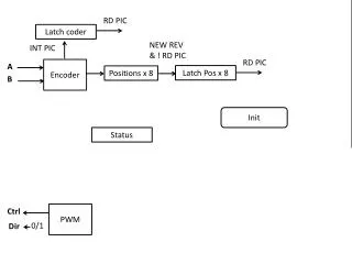
Electrical • One M23 coupling cable is required for connection to encoder • Max cable length is 150m for EnDat 02 option, MMT can easily use 25m cables • Power required is 3.6-5.25V @ 350mA • For implementation of period counting, intermediate connection is required to split out incremental signals for separate interpolation • Initial deployment simply connects directly to the IK220 board for both power and signals
Environmental • Viton seals are supplied, ozone resistance is very good • -10C will stiffen the bearing grease and seals a bit, and testing in Perugia showed self-heating is sufficient to keep the encoder working (in Antarctica…) • Altitude is also within the operating tolerance • Clean dry air can be supplied to the unit to reduce contamination (recommended!) • Unknown what to do for lightning protection; connection to PC via IK220 is technically a violation of long-standing electrical isolation policy for mount control systems
Integration Issues • Mount computer has no available PCI slots; we are ordering new passive-backplane PCI system to address this problem for other reasons • IK220 board needs to have a driver developed for use with VxWorks and xPC Target for testing and operations • Software using the new readout electronics and control design needs to be validated • Removal of existing encoder is a potentially unrecoverable change in terms of re-acquiring the original position should installation of RCN829 fail and require changing back • New pointing coefficients must be gathered, requiring a scheduled night (or two) for this activity
Performance Modeling Input shaft angle has error terms added to it, then is quantized and a backlash applied for resolution and hysteresis simulation
Inductosyn 512 cycles/rev sin/cos gain error 1024 cycles/rev sin/cos offset, crosstalk 2048 cycles/rev sin/cos distortion 4 cycles/rev resolver null error 8 cycles/rev resolver sin/cos gain error AD2S80 converter offset and tracking error Aging, temperature, and drift effects add up as well Historically ~0.25 to 0.5” RMS Difficult to correct with pointing coefficients due to large number of cycles per revolution RCN829 Long wave error due to encoder tolerances – guaranteed ± 1” Short-wave error due to signal period error < 1% 32768 lines 0.396” (incremental channel) Reversal error from shaft hysteresis, guaranteed < 0.4” RMS of 0.7” is achievable before correction Long-wave error is repeatable and measured data is provided, and so should be able to minimize with strategic clocking of encoder shaft and many fewer pointing-correction data points compared to Inductosyn Pointing Error Terms from Encoders Remark: Overall Inductosyn error is smaller(?), but more scattered than RCN829. However, RCN829 error is repeatable and more amenable to LUT or polynomial correction.
High-speed and Sidereal Tracking Simulation using Elevation Velocity Estimator
Comparison of 25- and 29-bit Position Error and Velocity Error at 1”/sec
Velocity Estimation Remarks • In every case, higher resolution gives finer velocity estimation outputs (5.6” p-p vs. 0.35” p-p, 16X as expected) • Estimation jitter frequency linearly related to quantization noise and proportional to velocity (Fjitter≈ (1.7 * velocity) + 28) (at 25 bits) • Jitter noise gets amplified in controller’s forward path – minimize wherever possible • But: • Shaft windup can be an issue; a high-quality coupling is absolutely necessary • Velocity jitter as was experienced with tape encoders may be encountered; fix with velocity-jitter estimator(?) • Modeling period counting may tell us more about what to expect Finally, generally speaking, the higher the resolution and less noisy velocity estimation, the higher the velocity loop gain can be increased for tracking stiffness; simulation studies can determine this quantitatively
Cost to Repair Tapes 12-week lead time is much longer than 2-4week ARO time for RCN829, and cost is very close to that with a new encoder
New Equipment Cost Mounting hardware cost appears to have been underestimated – recommend increase in this value by ~200% to cover FEA and stiff well-aligned mounting fixture to capture full encoder performance.
Time, People and Operations • Lead time for RCN829 is 4 weeks ARO, 12 weeks for replacement tapes • Already working on IK220 readout board drivers to support other encoders • New mechanical mount needed, design should start very soon if this course is taken • Encoder repairs have been effected, but we are currently running essentially without spares for encoders • Already working on upgrading azimuth servo, opportunity exists to do parallel development to support • Need 2 mechanical (1 designer, 1 drafter), 1 electrical, 2 software people to complete work by 2011
Pro Large increase in encoder resolution Increased velocity-loop stiffness Much simpler system electrical design No vulnerability to damage as on drive arcs Cost very competitive with repairing existing encoder hardware Replaces ancient analog encoder hardware with modern digital system More tractable pointing-correction model Supports more advanced velocity-estimation techniques Con Large effort required from small staff to implement New, expensive mount(s) must be designed and installed Unknown vulnerability to lightning or other environmental aspects Possible velocity-loop jitter issue Is a complete spare encoder affordable? Not having a spare is a risk…Can encoders for both main axes be afforded? Overall pointing error may be higher, at least until proper coefficients can be fitted Is it Worth it?
Recommended Action • Short term— • Apply whatever repairs/fixes can be to bring the tape encoders back into operation as much as possible • Repair/replace bad elevation resolver, buy a spare • Begin development of software for IK220 readout boards • Replace slot-limited mount computer hardware • Long term— • Plan to replace encoders with RCN829 units • Due diligence w.r.t. study of alternate vendors/offerings • Study mounting requirements and FEA of shaft coupling • Can RCN829 be mounted on West side of cell for testing/integration/tracking performance verification before installation on azimuth? • More detailed design simulation (e.g. period counting) to determine performance pitfalls and explore limits on controller gains