Download
1 / 19
190 likes | 307 Views
CAPSTONE Demonstration Radio TiVo FPGA. Thundercats : Hariklia Karagiannis Hasina Jamal Osato Edo- Osagie Brad Mazan Chad Griffith. When a radio listener misses a traffic report or wishes to replay a song that had just passed on the radio, there is no way to go back and re-listen.

E N D
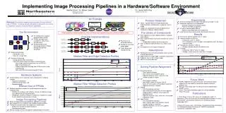
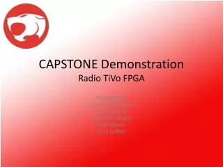
CAPSTONE DemonstrationRadio TiVo FPGA Thundercats: HarikliaKaragiannis Hasina Jamal Osato Edo-Osagie Brad Mazan Chad Griffith
When a radio listener misses a traffic report or wishes to replay a song that had just passed on the radio, there is no way to go back and re-listen. Radio TiVo is intended to rewind, pause, and playback audio from a radio device. Problem Overview
Interface Radio TiVo Audio Input (Radio, MP3 Player, CD Player, etc.) Audio Output (Earphones, Speakers, etc.) Buttons LEDs User
2. Pause/Play(Unpause) Jump to Live Volume Controls & Operations • Rewind by Increments (Hold < 3 sec) Reverse (Hold ≥ 3 sec) 4 1 2 3 Vol.
Project Status • Programmed the FPGA to • interpret user commands • drive RAM • direct the flow of data • control the LEDs • Applied a test bench and RAM model to the FPGA code for synthetic testing • Acquired all system components
Bring-Up Test Plan,Schedule, and Project Leaders AMP/ Filter 2/20 Brad Analog Input Module 3/2 ADC Osato Converters Module 2/20 AMP/ Filter 3/30 Brad Analog Output Module Final DAC 3/16 RAM Hariklia Processing Module FPGA Program 2/20 Chad FPGA Loading Program into FPGA Buttons & LEDs Hasina
Bring-Up Test PlanActive Low-Pass Filter • Objective: Design a smoothing filter to filter out sound frequencies above 20KHz. • Generate Signals with different frequencies and input them to the filter. • Test voltage output for each frequency value to assure frequencies above 20KHz are filtered out. • Also perform test with audio source and speakers to verify sound quality. Oscilloscope/ Speakers Signal Generator/ Audio Source
Objective: Build and test a system that converts analog to digital signals and the reverse. The FPGA is used as the driver. The ADC (ADS7823) to be used for our test design is a 12 bit low power, low cost, 12C serial & 50kSPS mixed signal device. And the DAC (DAC7512) is a 12bit low-power, low-cost & 95kSPS serial input converter. Devices/Equipments: ADS7823, DAC7512, Oscilloscope Spectrum Analyzer Signal Generator Signal Analyzer Matlab/Pattern Generator, Multimeter Bring-Up Test PlanADC/DAC & Filter
Bring-Up Test PlanADC/DAC & Filter • Setup/Procedures: • An oscilloscope will be used to monitor the output waveforms clocking the ADC and DAC. An audio source is connected to an amp to verify the analog output signal is centered around 2.5V. • Record the sine-wave amplitudes of the input and output voltages, for different frequencies, using the signal generator • The analog signal at ADC input and DAC output will be measured with a spectrum analyzer and compared qualitatively, along with collected digital data developed with a Matlab program or pattern generator. • An aural test will be made to confirm that the sound quality matches the quality of the sampling rate for the ADC and the DAC. • The output signal, as it is monitored on the signal analyzer, will display a 12 bit number to verify an optimized sample resolution for audio quality. This parameter would also be aurally verified. • The system would operate with a DC power supply of 1.5V to 5V. A multimeter will be used to measure the voltage at the source.
Bring-Up Test PlanADC/DAC & Filter Signal Analyzer Multimeter Measure output signal Display 12 bit number Audio source/Signal generator Audio output Amp Analog signals ADC FPGA Digital output ADC module Capture digital data Observe analog output 0 to 5V range. Analyze dynamic specs. Analog spectral properties. Digital data MatLab /Pattern generator Spectrum Analyzer Oscilloscope DAC module Measure and compare analog signal properties. Amplitudes & Freq Xteristics. SNR, THD, FFT Amp DAC Analog output Speaker Clearer signals with filter = Test Point Measure analog signals
Objective: Store the system logic into the FPGA using a prototype development board. Load a simple test program (oscillating LED/Strobing pins) into the FPGA and verify the control functionality. Load the same program into Flash and compare the functionality. Configure the proto pins and measure output digital High voltages that will interface with external components. Reconfigure the proto pins to accept input and verify that the input is valid and can be acknowledged by the FPGA. Test actual code stability, input and output of Dev. Board, and voltages on all proto pins. Bring-Up Test PlanFPGA Code & Dev. Board
Bring-Up Test PlanFPGA & RAM • Objective: Integrate the RAM into the system. Use the FPGA to drive the RAM and to perform the device operations. • Setup • Generate a 12-bit data string every 20us and control signals using a Pattern Generator. • Send this string to the FPGA as the input data and controls. • Setup test points at the FPGA input, RAM input, and Ram output and send the data to a Logic Analyzer. Generate Data Input Pattern Generator DC Power Supply FPGA Write Data RAM Read Data = Test Point Logic Analyzer
Bring-Up Test PlanFPGA & RAM • Test Procedure – Use the pattern generator to send mock input data and controls to the FPGA to drive the following operations: • Jump to Begin • Requires a 20+ minute digital string • Rewind by Increments • Reverse • Play (Unpause) • Jump to Live • Pause • Use the Logic Analyzer to verify that the correct sequence of data is returned for each operation.
Bring-Up Test PlanFPGA/RAM & User Interface • Objective: Add buttons and LEDs to the FPGA/RAM subsystem to allow control and feedback of the device operations. • Setup • Generate a 12-bit data string every 20us and control signals using a Pattern Generator. • Send this string to the FPGA as the input data. • Setup test points at the FPGA input, RAM input, and Ram output and send the data to a Logic Analyzer. FPGA LEDs Generate Data Input Read Data Pattern Generator DC Power Supply Write Data RAM Buttons = Test Point Logic Analyzer
Bring-Up Test PlanFPGA/RAM & User Interface • Test Procedure – Use the pattern generator to send mock input data to the FPGA and exhaustively test all combinations of pressing control buttons to drive the following operations: • Jump to Begin • Requires a 20+ minute digital string • Rewind by Increments • Reverse • Play (Unpause) • Jump to Live • Pause • Use the Logic Analyzer to verify that the correct sequence of data is returned for each operation. • Visually verify that the Power LED is always on when the FPGA is on, and that the Pause or Live Mode LEDs are only on when the device is operating in Pause or Live Mode.
PrototypeFinal Acceptance Test • Objective: The following procedures will verify the prototype requirements of the Radio TiVo device. • Device/Radio Interface • The device is detachable - Connect and disconnect the TiVo from the radio without damaging either system. • Device Output • Output audio - Play audio from the device output so that an unbiased listener accepts the quality of the audible sound signal. • Drive speakers - Attach speakers and verify that TiVo has an audio output. • Adjust the volume - Adjust the volume control and verify that the volume increases and decreases. This may be achieved by ear. • Device Recording • Record from audio input - Play sound from audio history. The device should retrieve a radio signal from a previous period in time and continue playing a delayed audio signal indefinitely for as long as the device is in play mode.
PrototypeFinal Acceptance Test • Device Memory Writing • Store at least 10 minutes of audio - Play sound from audio history that is 10 minutes old. • Device Memory Reading • Select incremented history - Press the rewind button for less than 3 seconds. For every press, the device should skip back in the audio history by 15 seconds. • Reverse audio - Hold the rewind button for at least than 3 seconds and the device should skip back in the audio history continuously until rewind is deselected. • Play live audio with a delay of less than 1s - Play audio from TiVo and the radio at the same time and measure the time delay. The time delay should be less than 1 second. • Pause audio - Select pause and the audio should stop playing. Select play and the audio should resume playing from where it left off.
Thank you Bill Wilson, Mentor Dr. Chuck LaBerge, Adviser Dr. Pinkston, Supervisor