Download
1 / 54
540 likes | 673 Views
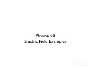
Physics 6B. Practice Final Solutions. 4m. 3m. 1. Two speakers placed 4m apart produce sound waves with frequency 425Hz. A listener is standing 3m in front of the left speaker. Describe the sound that he hears. Assume the speed of sound is 340 m/s. 4m. 3m.

E N D
Physics 6B Practice Final Solutions
4m 3m 1. Two speakers placed 4m apart produce sound waves with frequency 425Hz. A listener is standing 3m in front of the left speaker. Describe the sound that he hears. Assume the speed of sound is 340 m/s.
4m 3m 1. Two speakers placed 4m apart produce sound waves with frequency 425Hz. A listener is standing 3m in front of the left speaker. Describe the sound that he hears. Assume the speed of sound is 340 m/s. First find the distance from the right speaker (use the pythagorean theorem or recognize the 3-4-5 right triangle). 5m
4m 3m 1. Two speakers placed 4m apart produce sound waves with frequency 425Hz. A listener is standing 3m in front of the left speaker. Describe the sound that he hears. Assume the speed of sound is 340 m/s. First find the distance from the right speaker (use the pythagorean theorem or recognize the 3-4-5 right triangle). Now find the difference in the distances to each speaker: (5m – 3m) = 2m We need to compare this to the wavelength of the sound. 5m
4m 3m 1. Two speakers placed 4m apart produce sound waves with frequency 425Hz. A listener is standing 3m in front of the left speaker. Describe the sound that he hears. Assume the speed of sound is 340 m/s. First find the distance from the right speaker (use the pythagorean theorem or recognize the 3-4-5 right triangle). Now find the difference in the distances to each speaker: (5m – 3m) = 2m We need to compare this to the wavelength of the sound. This means the difference is 2.5 wavelengths, yielding destructive interference (a quieter sound) 5m
q1 q3 q2 x 1-x 2. Charge q1 = -5.4µC is placed at the origin, and charge q2 = -2.2 µC is on the x-axis at x=1m. Where should a charge q3 be placed between q1 and q2 so that the net force acting on it is zero? Here is a diagram, with q3 in between. We just need to find the forces on q3 due to the other charges, and make them equal.
q1 q3 q2 x 1-x 2. Charge q1 = -5.4µC is placed at the origin, and charge q2 = -2.2 µC is on the x-axis at x=1m. Where should a charge q3 be placed between q1 and q2 so that the net force acting on it is zero? Here is a diagram, with q3 in between. We just need to find the forces on q3 due to the other charges, and make them equal. We are not given the sign of charge q3, but it shouldn’t matter. The forces due to q1 and q2 will be in opposite directions in either case. F(q1 on q3) F(q2 on q3) Setting these equal, and plugging in the given values:
3. An object with a charge of – 3.6µC and a mass of 12g experiences an upward electric force, due to a uniform electric field, equal in magnitude to its weight. Find the direction and magnitude of the electric field.
3. An object with a charge of – 3.6µC and a mass of 12g experiences an upward electric force, due to a uniform electric field, equal in magnitude to its weight. Find the direction and magnitude of the electric field. Felec mg Electric force is simply charge times electric field.
3. An object with a charge of – 3.6µC and a mass of 12g experiences an upward electric force, due to a uniform electric field, equal in magnitude to its weight. Find the direction and magnitude of the electric field. Felec mg Electric force is simply charge times electric field. This is the magnitude of the field. The direction must be downward to give an upward force on a negative charge. One way to remember this is that the direction of the field is always the direction of the force on a positive charge. Since our charge is negative, it must be the opposite direction.
4. Two conducting spheres have net charges q1=+8 µC and q2=-2 µC. The spheres touch and some charge is transferred. How many electrons are transferred, and to which sphere?
4. Two conducting spheres have net charges q1=+8 µC and q2=-2 µC. The spheres touch and some charge is transferred. How many electrons are transferred, and to which sphere? AFTER BEFORE q1 ? µC q2 ? µC q1 +8 µC q2 -2 µC
4. Two conducting spheres have net charges q1=+8 µC and q2=-2 µC. The spheres touch and some charge is transferred. How many electrons are transferred, and to which sphere? AFTER BEFORE q1 +3 µC q2 +3 µC q1 +8 µC q2 -2 µC When the spheres touch, charges are transferred until both spheres have equal charge. The total charge before they touch is +6µC, so the charge on each sphere after they touch must be +3µC. So there must be a total of 5µC of charge transferred.
4. Two conducting spheres have net charges q1=+8 µC and q2=-2 µC. The spheres touch and some charge is transferred. How many electrons are transferred, and to which sphere? AFTER BEFORE q1 +3 µC q2 +3 µC q1 +8 µC q2 -2 µC When the spheres touch, charges are transferred until both spheres have equal charge. The total charge before they touch is +6µC, so the charge on each sphere after they touch must be +3µC. So there must be a total of 5µC of charge transferred. We need to divide by the charge on the electron to find the # of electrons transferred: Since sphere 1 gets less positive, it must be gaining the negative electrons. Conversely, sphere 2 is getting more positive, so it is losing electrons. Thus the electrons must be transferred to sphere 1.
5. During a lightning strike, electrons are transferred from the bottom of a thundercloud to the ground. During this process, the electrons: a) gain potential energy as they move toward a higher potential b) lose potential energy as they move toward a lower potential c) gain potential energy as they move toward a lower potential d) lose potential energy as they move toward a higher potential e-
5. During a lightning strike, electrons are transferred from the bottom of a thundercloud to the ground. During this process, the electrons: a) gain potential energy as they move toward a higher potential b) lose potential energy as they move toward a lower potential c) gain potential energy as they move toward a lower potential d) lose potential energy as they move toward a higher potential - - - - - e- + + + + + + + + + Since the electron is moving downward, the ground must be positively charged, and the bottom of the cloud must be negative. So the electron is moving toward a higher (positive) potential. Because its own charge is negative, however, the potential energy of the electron is getting more negative as it moves toward the ground. So it is losing potential energy.
6. During a lightning strike, electrons are transferred from the bottom of a thundercloud to the ground. This occurs due to dielectric breakdown of the air, when the electric field is greater than 3x10⁶ V/m. The distance from the ground to the cloud is 1000m. Find the magnitude of the potential difference between the cloud and the ground. - - - - - 1000m + + + + + + + + +
6. During a lightning strike, electrons are transferred from the bottom of a thundercloud to the ground. This occurs due to dielectric breakdown of the air, when the electric field is greater than 3x10⁶ V/m. The distance from the ground to the cloud is 1000m. Find the magnitude of the potential difference between the cloud and the ground. Assuming a constant electric field, we can use the formula V=Ed - - - - - 1000m + + + + + + + + +
7. An electric dipole consists of two equal charges, +q and –q, a distance d apart. Find the total electric potential at a point that is a distance of d/2 to the right of the positive charge, as shown. -q +q d d/2
7. An electric dipole consists of two equal charges, +q and –q, a distance d apart. Find the total electric potential at a point that is a distance of d/2 to the right of the positive charge, as shown. -q +q d d/2 The electric potential due to a point charge is given by: In this formula we include the sign of the charge to tell us the sign of the potential. All we need to do is find the potential due to each charge, and then add them together.
7. An electric dipole consists of two equal charges, +q and –q, a distance d apart. Find the total electric potential at a point that is a distance of d/2 to the right of the positive charge, as shown. -q +q d d/2 The electric potential due to a point charge is given by: In this formula we include the sign of the charge to tell us the sign of the potential. All we need to do is find the potential due to each charge, and then add them together.
8. How much charge is on each plate of the capacitors in the circuit shown? The battery has voltage 12V, and the capacitances are: C1=3µF, C2=2µF, C3=4µF. 12V C2 C1 C3
8. How much charge is on each plate of the capacitors in the circuit shown? The battery has voltage 12V, and the capacitances are: C1=3µF, C2=2µF, C3=4µF. 12V C2 C1 C3 12V C2+C3 C1 First we need to find the equivalent capacitance for the circuit. C2 and C3 are in parallel, so we just add them together.
8. How much charge is on each plate of the capacitors in the circuit shown? The battery has voltage 12V, and the capacitances are: C1=3µF, C2=2µF, C3=4µF. 12V C2 C1 C3 12V C2+C3 C1 12V Ceq=2µF First we need to find the equivalent capacitance for the circuit. C2 and C3 are in parallel, so we just add them together. Next we see that C1 is in series with the (C2+C3) combination, so we need to use the reciprocal formula.
8. How much charge is on each plate of the capacitors in the circuit shown? The battery has voltage 12V, and the capacitances are: C1=3µF, C2=2µF, C3=4µF. 12V C2 C1 C3 12V C2+C3 C1 12V Ceq=2µF First we need to find the equivalent capacitance for the circuit. C2 and C3 are in parallel, so we just add them together. Next we see that C1 is in series with the (C2+C3) combination, so we need to use the reciprocal formula. The total charge for the system is given by Q=CV. Qtotal=24µC Now we need to work backward to find the charge on each capacitor. First look at capacitor C1. There are no parallel paths connected to it, so all the charge must land on its plates. Q1=24µC
8. How much charge is on each plate of the capacitors in the circuit shown? The battery has voltage 12V, and the capacitances are: C1=3µF, C2=2µF, C3=4µF. 12V C2 C1 C3 12V C2+C3 C1 12V Ceq=2µF First we need to find the equivalent capacitance for the circuit. C2 and C3 are in parallel, so we just add them together. Next we see that C1 is in series with the (C2+C3) combination, so we need to use the reciprocal formula. The total charge for the system is given by Q=CV. Qtotal=24µC Now we need to work backward to find the charge on each capacitor. First look at capacitor C1. There are no parallel paths connected to it, so all the charge must land on its plates. Q1=24µC Next we notice that since the other 2 capacitors are in parallel, the charge must split up so that the total adds up to 24µC. Option 1 Since C2 has half the capacitance of C3, it will only get half the charge. So we need Q2=8µF and Q3=16µF. This adds up to 24, and Q2 is half as much as Q3. Option 2 The voltage across C2 and C3 must be equal because they are in parallel. Using V=Q/C we get V1=8volts. This leaves 4volts for the others. Now using Q=CV again we get Q2=8 and Q3=16
A parallel-plate capacitor is initially charged by a battery with voltage V. The battery is disconnected, and a dielectric with constant k is inserted between the plates. What happens to the energy stored in the capacitor?
A parallel-plate capacitor is initially charged by a battery with voltage V. The battery is disconnected, and a dielectric with constant k is inserted between the plates. What happens to the energy stored in the capacitor? When the battery is disconnected, the charges that have built up on the plates have nowhere to go, so the charge on the capacitor will remain constant when the dielectric material is inserted. To calculate the amount of charge we could use the formula Q=CV.
A parallel-plate capacitor is initially charged by a battery with voltage V. The battery is disconnected, and a dielectric with constant k is inserted between the plates. What happens to the energy stored in the capacitor? When the battery is disconnected, the charges that have built up on the plates have nowhere to go, so the charge on the capacitor will remain constant when the dielectric material is inserted. To calculate the amount of charge we could use the formula Q=CV. Now what happens when the dielectric is inserted? The capacitance is increased by a factor of k (the dielectric constant). So what does that do to the energy?
A parallel-plate capacitor is initially charged by a battery with voltage V. The battery is disconnected, and a dielectric with constant k is inserted between the plates. What happens to the energy stored in the capacitor? When the battery is disconnected, the charges that have built up on the plates have nowhere to go, so the charge on the capacitor will remain constant when the dielectric material is inserted. To calculate the amount of charge we could use the formula Q=CV. Now what happens when the dielectric is inserted? The capacitance is increased by a factor of k (the dielectric constant). So what does that do to the energy? We have 3 versions of the potential energy formula for capacitors: Let’s use version (3). We already know that the charge (Q) is not going to change. Since the capacitance is increased by a factor of k, the energy must decrease by that factor (the C is in the denominator of the formula). So the answer is c) The stored energy decreases by a factor of k Note: if the battery had remained connected, the energy would have increased by a factor of k instead. Think about why this happens.
10. How much power is dissipated in each of the resistors in the circuit shown? The battery has voltage 12V, and the resistances are: R1=4Ω, R2=3Ω, R3=6Ω. 12V R2 R1 R3
10. How much power is dissipated in each of the resistors in the circuit shown? The battery has voltage 12V, and the resistances are: R1=4Ω, R2=3Ω, R3=6Ω. 12V R2 R1 R3 12V 2Ω R1 First we need to find the equivalent resistance for the circuit. R2 and R3 are in parallel, so we use the reciprocal trick.
10. How much power is dissipated in each of the resistors in the circuit shown? The battery has voltage 12V, and the resistances are: R1=4Ω, R2=3Ω, R3=6Ω. 12V R2 R1 R3 12V 2Ω R1 12V 6Ω First we need to find the equivalent resistance for the circuit. R2 and R3 are in parallel, so we use the reciprocal trick. Next we see that R1 is in series with the (R2 and R3) combination, so we just add them together, For a total of 6Ω.
10. How much power is dissipated in each of the resistors in the circuit shown? The battery has voltage 12V, and the resistances are: R1=4Ω, R2=3Ω, R3=6Ω. 12V R2 R1 R3 12V 2Ω R1 12V 6Ω First we need to find the equivalent resistance for the circuit. R2 and R3 are in parallel, so we use the reciprocal trick. Next we see that R1 is in series with the (R2 and R3) combination, so we just add them together, For a total of 6Ω. Now we can use Ohm’s law to find the current: All of this current must go through R1, since there is no other path parallel to it. We can use the formula for power dissipated by a resistor: P=I2R = IV = V2/R. In this case the first one works fine:
10. How much power is dissipated in each of the resistors in the circuit shown? The battery has voltage 12V, and the resistances are: R1=4Ω, R2=3Ω, R3=6Ω. 12V R2 R1 R3 12V 2Ω R1 12V 6Ω First we need to find the equivalent resistance for the circuit. R2 and R3 are in parallel, so we use the reciprocal trick. Next we see that R1 is in series with the (R2 and R3) combination, so we just add them together, For a total of 6Ω. Now we can use Ohm’s law to find the current: All of this current must go through R1, since there is no other path parallel to it. We can use the formula for power dissipated by a resistor: P=I2R = IV = V2/R. In this case the first one works fine: The current will split when it gets to the R2/R3 parallel combination: Option 1 Since R2 has half the resistance of R3, it will get twice the current. So we get . and This adds up to 2, and I2 is half as much as I3. Now use P=I2R again: Option 2 The voltage across C2 and C3 must be equal because they are in parallel. Using V=IR we get V1=8volts. This leaves 4volts for the others. Now using P=V2/R we get:
A C B • In the circuit below all the bulbs have the same resistance. • When the switch is closed, what happens to bulb A?
A C B • In the circuit below all the bulbs have the same resistance. • When the switch is closed, what happens to bulb A? First realize that since we assume that the resistance stays constant, we know that bulbs get brighter when the current increases. Next, see from the diagram that all the current must go through bulb A. So now think about what happens when the switch is closed. The path through bulb B is closed, creating a parallel path to bulb C. This has the effect of reducing the equivalent resistance (adding a parallel path will always reduce the overall resistance). Since the resistance is reduced, the current must increase. (V=I/R) So the current through bulb A increases, and bulb A gets brighter. Bonus question – what happens to bulb C?
12. Resistor 1 is a solid cylinder with length L and diameter D. Resistor 2 is made of the same material, but it has length 2L and diameter 2D. Compared to the resistance of resistor 1, resistance 2 is:
12. Resistor 1 is a solid cylinder with length L and diameter D. Resistor 2 is made of the same material, but it has length 2L and diameter 2D. Compared to the resistance of resistor 1, resistance 2 is: Use the formula for resistance: The resistivity is the same for each resistor. The length is twice as large. The area is 4 times as big, because area depends on the diameter squared Now compare the 2 resistances: So the answer is b) half as large
13. A coil with 1000 turns of wire and a cross-sectional area of 0.5m2 is rotating at 60rpm in a uniform magnetic field of magnitude 2 Tesla. Find the voltage induced in the coil as it rotates through one quarter of a revolution? There will be an induced EMF (voltage) whenever there is a changing magnetic flux through the coil. This coil is rotating, so the flux is constantly changing. The coil makes 60 revolutions each minute, so that is 1 revolution each second. So a quarter-turn takes a time of 0.25 seconds. In a quarter of a revolution the coil will go from maximum flux to zero flux, so the change in flux will be equal to the maximum flux. Now we can use our formula for induced voltage (N=1000 turns of wire):
14. Two singly ionized isotopes of uranium (one electron has been removed) are projected at v=1.5x10⁵m/s into a region with a uniform magnetic field of strength 0.75T directed into the page, as shown. The particles land at distances d1=68.2cm and d2=69.2cm from the entry point. Find the difference between the masses of the particles. B 2 1 v
14. Two singly ionized isotopes of uranium (one electron has been removed) are projected at v=1.5x10⁵m/s into a region with a uniform magnetic field of strength 0.75T directed into the page, as shown. The particles land at distances d1=68.2cm and d2=69.2cm from the entry point. Find the difference between the masses of the particles. B 2 1 v Each charge feels a magnetic force directed toward the center of the circular path. Setting centripetal force equal to magnetic force:
14. Two singly ionized isotopes of uranium (one electron has been removed) are projected at v=1.5x10⁵m/s into a region with a uniform magnetic field of strength 0.75T directed into the page, as shown. The particles land at distances d1=68.2cm and d2=69.2cm from the entry point. Find the difference between the masses of the particles. B 2 1 v Each charge feels a magnetic force directed toward the center of the circular path. Setting centripetal force equal to magnetic force: The charge, magnetic field, and velocity are the same for both charges. Only the radius is different. Notice that the distance given are diameters, so we must divide them by 2.
15. Consider the three electric charges shown below. Charge B is equidistant from charges A and C. List the charges in order of the magnitude of the force they experience, from smallest to largest. -q +q +q A B C Each charge will feel 2 forces from the other charges.
15. Consider the three electric charges shown below. Charge B is equidistant from charges A and C. List the charges in order of the magnitude of the force they experience, from smallest to largest. -q +q +q A B C r r Each charge will feel 2 forces from the other charges. Remember – same sign repels, opposites attract.
16. A beam of electrons is passing through a region with a uniform magnetic field directed into the page. If the electrons are initially moving in the +x direction, which direction are they deflected when they enter the field? B v e- Use a right-hand-rule for this. Start with fingers along the velocity, then bend them into the page (toward the magnetic field). The thumb gives the direction of the force on a positive charge.
16. A beam of electrons is passing through a region with a uniform magnetic field directed into the page. If the electrons are initially moving in the +x direction, which direction are they deflected when they enter the field? B v e- Use a right-hand-rule for this. Start with fingers along the velocity, then bend them into the page (toward the magnetic field). The thumb gives the direction of the force on a positive charge. In this case we get the thumb pointing upward. However, our charge is an electron, so the force is in the opposite direction. You can flip your hand over, or use your left hand if you want. Fmag
A circuit is arranged with a sliding wire that can move vertically, as shown. There is a uniform magnetic field directed out of the page. The sliding wire is released from rest in the position shown. As the wire falls: • a) induced current flows clockwise in the circuit and the bulb gets brighter and brighter. • b) induced current flows clockwise in the circuit and the bulb glows with a constant brightness. • c) induced current flows counter-clockwise in the circuit and the bulb gets brighter and brighter. • d) induced current flows counter-clockwise in the circuit and the bulb glows with a constant brightness. v B First note that there is magnetic flux through the loop, directed out of the page. As the wire slides down, the loop gets smaller, so the amount of flux decreases.
A circuit is arranged with a sliding wire that can move vertically, as shown. There is a uniform magnetic field directed out of the page. The sliding wire is released from rest in the position shown. As the wire falls: • a) induced current flows clockwise in the circuit and the bulb gets brighter and brighter. • b) induced current flows clockwise in the circuit and the bulb glows with a constant brightness. • c) induced current flows counter-clockwise in the circuit and the bulb gets brighter and brighter. • d) induced current flows counter-clockwise in the circuit and the bulb glows with a constant brightness. v B First note that there is magnetic flux through the loop, directed out of the page. As the wire slides down, the loop gets smaller, so the amount of flux decreases. The reaction to this decreasing flux is to induce current in the wire in such a way that magnetic flux is created to oppose the change – out of the page. A right-hand rule will tell us that the induced current flows counter-clockwise. Iinduced
A circuit is arranged with a sliding wire that can move vertically, as shown. There is a uniform magnetic field directed out of the page. The sliding wire is released from rest in the position shown. As the wire falls: • a) induced current flows clockwise in the circuit and the bulb gets brighter and brighter. • b) induced current flows clockwise in the circuit and the bulb glows with a constant brightness. • c) induced current flows counter-clockwise in the circuit and the bulb gets brighter and brighter. • d) induced current flows counter-clockwise in the circuit and the bulb glows with a constant brightness. v B First note that there is magnetic flux through the loop, directed out of the page. As the wire slides down, the loop gets smaller, so the amount of flux decreases. The reaction to this decreasing flux is to induce current in the wire in such a way that magnetic flux is created to oppose the change – out of the page. A right-hand rule will tell us that the induced current flows counter-clockwise. The wire is accelerating downward, so the flux is decreasing faster and faster as the wire falls. This means the induced current must get stronger and stronger, making the bulb glow brighter and brighter. Iinduced