Starting and Charging Systems
200 likes | 532 Views
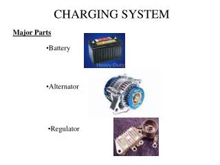
23. Starting and Charging Systems. FIGURE 23.1 The cold-cranking amperes (CCA) is the rating that is most commonly used to rate batteries.

Starting and Charging Systems
E N D
Presentation Transcript
23 Starting and Charging Systems
FIGURE 23.1 The cold-cranking amperes (CCA) is the rating that is most commonly used to rate batteries.
FIGURE 23.2 Corrosion on a battery cable could be an indication that the battery itself is either being overcharged or is sulfated, creating a lot of gassing of the electrolyte.
FIGURE 23.3 A visual inspection on this battery shows the electrolyte level was below the plates in all cells.
FIGURE 23.4 (a) A voltage reading of 12.28 volts indicates that the battery is not fully charged and should be charged before testing.
FIGURE 23.4 (b) A battery that measures 12.6 volts or higher after the surface charge has been removed is100% charged.
FIGURE 23.5 An alternator regulator battery starter tester (ARBST) automatically loads the battery with a fixed load for 15 seconds to remove the surface charge, then removes the load for 30 seconds to allow the battery to recover, and then reapplies the load for another 15 seconds. The results of the test are then displayed.
FIGURE 23.6 A conductance tester is very easy to use and has proved to accurately determine battery condition if the connections are properly made. Follow the instructions on the display exactly for best results.
FIGURE 23.7 Jumper cable usage guide. Note that the last connection should be the engine block of the disabled vehicle to help prevent the spark that normally occurs from igniting the gases from the battery.
FIGURE 23.8 A typical industrial battery charger. Be sure that the ignition switch is in the off position before connecting any battery charger. Connect the cables of the charger to the battery before plugging the charger into the outlet. This helps prevent a voltage spike and spark that could occur if the charger happened to be accidentally left on. Always follow the battery charger manufacturer’s instructions.
FIGURE 23.10 To prevent the engine from cranking, an electrical switch is usually installed to open the circuit between the ignition switch and the starter solenoid.
FIGURE 23.11 All battery cables and connections have to be clean and tight for the starter to be able to operate correctly.
FIGURE 23.12 The end frame toward the drive belt is called the drive-end housing and the rear section is calledthe slip-ring-end housing.
FIGURE 23.13 The digital multimeter should be set to read DC volts, with the red lead connected to the positive (+)battery terminal and the black meter lead connected to the negative (–) battery terminal.