Download
1 / 39
390 likes | 394 Views
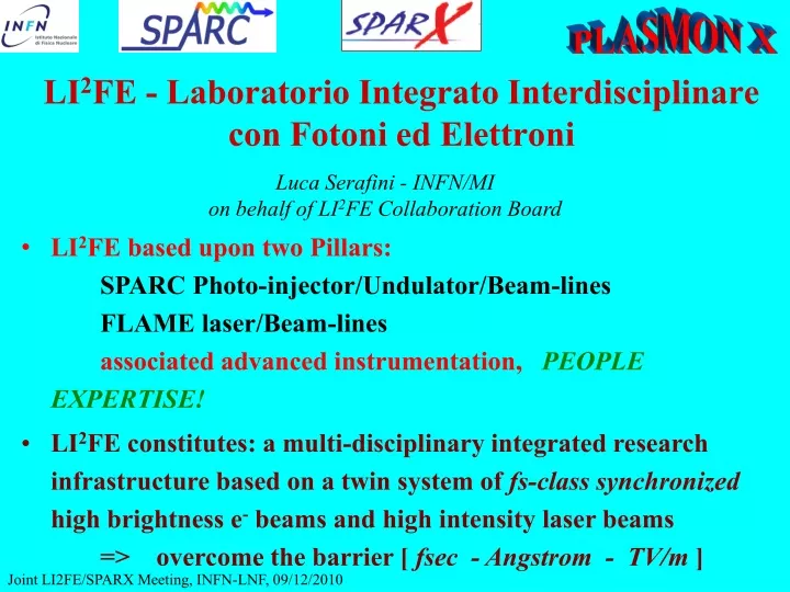
LI 2 FE - Laboratorio Integrato Interdisciplinare con Fotoni ed Elettroni. Luca Serafini - INFN/MI on behalf of LI 2 FE Collaboration Board.

E N D
LI2FE - Laboratorio Integrato Interdisciplinare con Fotoni ed Elettroni Luca Serafini - INFN/MI on behalf of LI2FE Collaboration Board • LI2FE based upon two Pillars: SPARC Photo-injector/Undulator/Beam-lines FLAME laser/Beam-lines associated advanced instrumentation, PEOPLE EXPERTISE! • LI2FE constitutes: a multi-disciplinary integrated research infrastructure based on a twin system of fs-class synchronized high brightness e- beams and high intensity laser beams => overcome the barrier [ fsec - Angstrom - TV/m ]
Now the Two Pillars of LI2FE aresuccessfully working, independently We must make them work together! LI2FE collaboration was set primarily to stimulate and coordinate this task
SPARC(Sorgente Pulsata e Amplificata di Radiazione Coerente) and PLASMONX(PLasma Acceleration @ Sparc & MONochromatic X-rays) Unique worldwide at these level of combined beam performance High Brightness Electron Beams (ps to fs bunch length) Synchronized to fs level High Intensity Laser Beams (20-100 fs pulses)
FLAME will mark soon a record in light intensity FLAME @ INFN-LNF The Laser Pulse Intensity Chart
Brilliance of X-ray radiation sources Thomson Source @ LNF Compact Thomson Sources extend SR to hard X-ray range allowing Advanced Radiological Imaging inside Hospitals Beam param. invariant under linear optics 12.4 1.24 0.124 l (nm) FLAME SASE-FELs will allow an unprecedented upgrade in Source Brilliance SPARX TTF Covering from the VUV to the 1 Å X-ray spectral range: new Research Frontiers
1018 1017 AOFEL I [kA] 1016 1015 1014 1013 n[m] Self-Inj LCLS Laminar velocity bunching SPARX Ext-Inj X-ray FEL @ 1 pC normal velocity bunching SPARC Photo-injectors The Electron Beam Brightness Chart [A/(m.rad)2]
LI2FE: the Scientific Program Development of a wide inter-disciplinary research program, combining high brightness high rapidity electron beams (drive plasmas at 7.1019 cm-3 => TV/m) with high intensity ultra-short laser pulses (4.1018 cm-3 => 250 GV/m), leading in turns to production of a variety of advanced beams of FEL/THz radiation, advanced beams of X/g rays (thanks to a photon-electron collider at 1035 cm-2s-1 luminosity), protons/light ions, and potentials for polarized positrons and neutrons of unique characteristics. Common Denominator: High Phase Space Density
LI2FE Projects and Experiments (co)funded by INFN SPARC - INFN Special Project (cofund. by MIUR, CNR, ENEA) M. Ferrario (see next talk & SPARC-FEL by L. Giannessi ) PLASMONX - Nuove Tecniche Accelerazione - D. Giulietti (morning session, see next session for External Injection by L.S.) SPARX - MIUR, Reg. Lazio, ENEA, CNR, Univ. Tor Vergata L. Palumbo (see next session) BEATS2 - Commissione Scientifica Naz. V – M. Gambaccini LILIA - Nuove Tecniche Accelerazione – C. De Martinis TERASPARC - Commissione Scientifica Naz. V – S. Lupi COMB – Nuove Tecniche Accelerazione - M. Ferrario (see next talk )
Seeding 150 MeV S-band linac Velocity Bunching Diagnostic and Matching Undulators u = 2.8 cm Kmax = 2.2 r = 500 nm S-band Gun 15 m Long Solenoids Beam energy 155–200 MeV Bunch charge 1 nC Rep. rate 10 Hz Peak current 100 A en 2 mm-mrad en(slice) 1 mm-mrad sg 0.2% Bunch length (FWHM) 10 ps THz Source TERASPARC: Terahertz Radiation through the Free-Electron Laser
Characterization of the SPARC Coherent Transition Radiation THz Source
Performances AchievedData vs Simulation E. Chiadroni et al, Unpublished
Future Activity:2011 • Spectral measurement • Frequency Domain: Martin-Pupplet Interferometer; • Time Domain: Averaged Electro-Optic Sampling (EOS) • Single Shot EOS • Coupling with the external photocathode laser • Pump-Probe Experiments • THz-Pump THz-Probe experiments: Life Time of Quantum Wells in Si/SiGe (Roma III); • 2) Multiple Colors Experiments Coupling with the FEL laser
Plasmon Thomson quadrupoles dipoles RF deflector collimator 25º solenoid Photoinjector RF sections 25º 11º FEL 5.4 m 1.5m 10.0 m 14.5 m 1-6 Undulator modules Diagnostic Schematic layout of electron beam linesfor FEL, Plasma Acceleration andThomson Source experiments
Side view Raggi X Map view Raggi X Thomson Source Interaction Chamber
Thomson Source Interaction Region Scattering Chamber Laser beam X-ray beam Deflected e- beam (hν)X=4 (hν)laser ( T/ 0.511)2 Laser pulse: 6 ps, 5 J e- bunch: 1 nC , l2 mm (rms) X-ray: 10 ps, 109 photons per shot a emission: 12 mrad (hν)laser = 1.2 eV T = 30.28 MeV (hν)X = 20 keV for mammography
Start-to-end simulations including errors and misalignments for X–ray spectra and intensity distributions Intensity distrib. on laser parabolic mirror (black circle = mirror hole) Energy spectrum for various angular acceptances
X-ray characterization system monitor chamber collimators and filter holders pin diode detector
Acquisition of beam transport lines (magnets and related hardware, mirrors, diagnostics, etc)is ongoing We expect to install all hardware inside SPARC bunker by july 2011 Starting of Thomson Source commissioning in september 2011
Laser beam LILIA(Laser Induced Light Ions Acceleration) LILIA aims to accelerate protons trough laser interaction with thin targets in order to obtain an useful beam which could be also injected in other accelerating structures. proton beam
The LILIA experiment • In the first experimental phase, which will take place in the second half of 2011 we will focus on two aspects: 1. a parametric study of the correlation of the maximum TNSA accelerated proton energy, with respect to the following parameters: • Laser pulse intensity (in the range 1018 – 5x10¹⁹ W/cm2) • Laser pulse energy (in the range 0.1-5 J) • Laser pulse length (in the range 25 fs- 1ps) • Metallic target thickness (in the range 1-100 microns). In such a frame we would like to deeply investigate the experimental scale rules within the possibilities offered by the FLAME facility. 2. We will exploit the possibility to select in energy and focus a relevant part of the protons in order to produce a real proton beam able to be driven for significant distances (50-75 cm) away from the interaction point and which will act as a source for further accelerating structures
FLAME @ INFN-LNF With max intensity available from FLAME (with adaptive optics) we could reach proton energy in excess of 100 MeV. As of now we are limited to 5x10¹⁹ W/cm2 and we can foresee a maximum proton energy of 10 MeV
LILIA Diagnostic devices under development Radiochromic films Thomson parabola Silicon diodes arrays
LI2FE: main Research Areas FEL physics and applications Advanced beam physics Laser/Plasma based ion sources Advanced radiation sources and applications Laser/Plasma physics Ultra-high gradient acceleration (plasma, vacuum, IFEL)
LI2FE: Collaboration Board Dimitri Batani - Università Milano Bicocca Maurizio Benfatto - Lab. Naz. Frascati INFN Massimo Carpinelli - Univ. di Sassari Giuseppe Dattoli - ENEA Frascati Giampiero Dipirro - Lab. Naz. Frascati INFN Massimo Ferrario - Lab. Naz. Frascati INFN Santo Gammino - Lab. Naz. del Sud INFN Luca Giannessi - ENEA Frascati Danilo Giulietti - Università di Pisa Leonida Gizzi - ILIL-IPCF, CNR, Pisa Stefano Lupi - Univ. Roma La Sapienza Carlo Mariani - Univ. Roma La Sapienza Luigi Palumbo - Univ. Roma La Sapienza Valerio Rossi Albertini - ISM, CNR, Roma Luca Serafini, chair- INFN Sez. di Milano More Details in: http://www.lnf.infn.it/acceleratori/life/
LI2FE: the Scientific Program The combined availability of these Beam Sources and related instrumentation, together with advanced expertise in the accelerator/laser/plasma physics and technologies, will lead to unprecedented potentials of research and discoveries at INFN-LNF (multi-institutional effort, INFN, ENEA, CNR, many Univ.) User experiments: application oriented (investigation of matter at functional level) Developer experiments: technique oriented (toward the high energy frontier, propedeutical to investigation of matter at fundamental level)
LI2FE beyond the horizon(an acceleratorist’s vision)PWFA (particle wakefield acceleration) using hyper-short SPARC electron bunches (1pC, sub-fs) to drive plasma waves up to TV/m accelerating fields (beating the high energy frontier)
Unprecedented results in Application Experiments due to unique beams available LI2FE Window of Opportunity (5 year span) Crucial Role in advancing new technologiesfor the High Energy Frontier needless to say… we need the correct Spirit of sharing Expertise and Instrumentation
Schema della camera monitor realizzata nell’ambito dell’esperimento BEATS attualmente in fase di calibrazione presso il laboratorio LARIX di Ferrara. Nello schema è visibile anche la sede per l’istallazione del fotodiodo PIN a grande area ed il sistema porta collimatori per la misura del flusso X
(magnetostatic undulator ) Example : for lR=1A, lw=2cm, E=7 GeV (electromagnetic undulator ) Example : for lR=1A, l=0.8mm, E=25MeV laser power laser spot size FEL resonance condition
Physics scenario e- beam Lorentz boosted radiation forward directed E IntenseLaser Radiated field, linear pol. E-beam rest frame Thomson limit (180° ICS) In Thomson Limit the X-ray beam divergence and Spectrum are determined by the electron beam characteristics General View: Lab frame Doppler upshifted, angular redshift Thomson limit valid up to -rays of 25 MeV (Te<1.25 GeV) with e- recoil < 1% X-ray flux depends on overlapping electrons, laser photons
Scattered photons in collision Thomson X-section • Scattered flux • Luminosity as in HEP collisions • Many photons, electrons • Focus tightly • Short laser pulse; <few psec (depth of focus)
Spectral broadening due to ultra-focused beams X e- X e- focus envelope
Overlap Energy-angular Spectral distribution For an e-bunch the energy spread of the collected photons depends on • Collecting angle qM • Bunch energy spread • Transverse emittance Full treatement of linear and nonlinear TS for a plane-wave laser pulse with analytical expression of the distributions as well as several approximate expressions in P. Tomassini et al., Appl. Phys. B 80, 419 (2005).
Angular and spectral distribution of the TS radiation in the case of 3 ps laser pulse (12.5 µm beam waist)Linear Thomson Scattering