Download
1 / 1
10 likes | 111 Views
This paper discusses the evaluation of a fiber positioning system using a CCD camera test setup. The setup measures spot sizes, lever designs, material flexibility, and distance accuracy. It covers calibration, testing procedures, and distortion correction using MATLAB and polynomial curve fitting. The research was conducted at Lawrence Berkeley National Laboratory in collaboration with the BigBOSS R&D group.

E N D
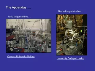
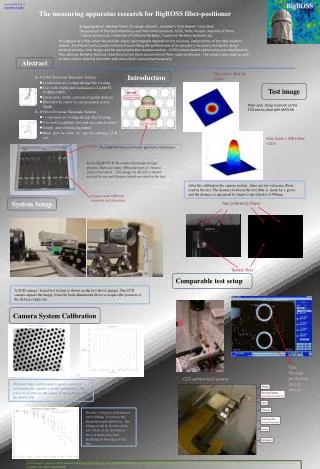
Paper 8446-219 of Conference 8446 Zengxiang Zhou1, Michael Sholl2, Christoph Schenk3, Joe Silber3, Chris Bebek3, Chao Zhai1 1Department of Precision Machinery and Precision Instrument, USTC, Hefei, People’s Republic of China 2 Space Science Lab, University of California Berkeley , 3Lawrence Berkeley National Lab , Abstract Spot size = 18 X 18 pixels Introduction Test image Fiber spot sharp read out on the CCD sensor, deal with MATLAB Gray Scale = 248 ( Max =255) Levers The BigBOSS fiber-positioner geometry dimension. The measuring apparatus research for BigBOSS fiber-positioner • In the BigBOSS R-Өactuator prototype design process, there are many different types of flexure need to be tested . The image on the left is shown several levers and flexures which are used in the test. Flexure with different material and structure • After the calibration the camera system , there are two reference fibers used in the test. The distance between the two fiber is made by v-grove and the distance is measured by smart scope which is 6.998mm. System Setup Two reference fibers 6.998 mm Throughput of a fiber-robot-based multi-object spectrograph depends on the accuracy and precision of the fiber position system. An efficient and accurate method of quantifying the performance of an actuator is necessary during the design iteration process, final design, and for post-production characterization. A CCD camera-based optical setup was developed at the Lawrence Berkeley National Laboratory to test these parameters of fiber robot positioners. The setup is described, as well as tests used to quantify distortion and cross-check measurement accuracy. Tested fiber Comparable test setup • A CCD camera - based test system is shown on the two above images. The CCD camera capture the image from the back-illuminated fibers to acquire the position of the flexure expansion. Camera System Calibration Two fiducials on the top end of flexure CCD camera test system Standard target with hexagon spots is used for calculating the camera systems’ parameters. The red cross points are the center of spots acquired by the MATLAB. • Use the 4 degrees polynomial curve fitting to correct the aberration and distortion , the fitting result is shown on the left. Most of the distortion error is limited in 5um including at the edge of the lens. All the work is done in the Lawrence Berkeley National Lab with BigBOSS R&D group and supported by the Director, Office of Science, High Energy Physics, of the U.S. Department of Energy, under contract number DE-AC03-76SF00098