Download
1 / 14
150 likes | 356 Views
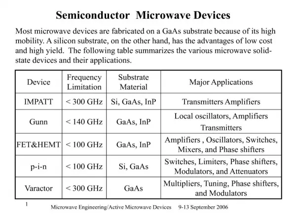
Elec and Comp Tech 62B Semiconductor Devices. Chapter 10 Oscillators and Timers Feedback Oscillators. The Oscillator. The oscillator circuit produces a periodic waveform output with the power supply being the only required input The output can be a sine, square, ramp, or other waveform

E N D
Elec and Comp Tech 62BSemiconductor Devices Chapter 10 Oscillators and Timers Feedback Oscillators
The Oscillator • The oscillator circuit produces a periodic waveform output with the power supply being the only required input • The output can be a sine, square, ramp, or other waveform • An additional input can be used to synchronize the oscillation • Two major classifications of oscillators • Feedback oscillators • Relaxation oscillators 62Bchap10a
Feedback Oscillator • Attenuation sets loop gain at 1 • Net phase shift at oscillation frequency equals zero 62Bchap10a
Oscillator Start-Up • Some initial stimulus is needed to start oscillation • Start-up gain must be >1 for oscillation to build to desired level 62Bchap10a
Start-Up Stimulus • In a real oscillator circuit, noise from the op-amp is usually sufficient to provide the starting stimulus • In Multisim, some external stimulus is required to start the oscillation 62Bchap10a
Start-Up Gain • Gain much larger than 1 • Starts oscillation with less stimulus • Oscillation builds to desired output voltage faster • Without some method of lowering the gain after reaching the desired output voltage, the output continues to grow until reaching amplifier saturation 62Bchap10a
Fixed-Gain Oscillators • Gain slightly greater than 1 • May not start oscillating without external stimulus • Amplifier saturation is used to limit gain • When slight distortion is acceptable, additional gain limiting circuitry is not needed. 62Bchap10a
Wein-Bridge Oscillator • Bandpass filter • fr = 1/2πRC • Peak Vout at frVout/Vin = 1/3 • Feedback phase shift = 0 62Bchap10a
Wein-Bridge Oscillator • Wein bridge is created with lead-lag (bandpass) positive feedback and resistive negative feedback • Positive feedback Vout/Vin=1/3 • Negative feedback sets Acl=3, so net gain through bridge = 1 62Bchap10a
Self-Starting Wein-Bridge • Start-up requires loop gain >3 to build output level • Continuous oscillation without saturation requires gain = 3 • An automatic gain control (AGC) is needed 62Bchap10a
Back-to-Back Zener Method • At start-up, and as output builds, R3 is in series with R1, so AV>3 • When voltage across R3>VZ+0.7 V, diodes short out drop across R3, limiting gain to AV=3 62Bchap10a
JFET AGC • Q1 operates in ohmic region • Negative peak detector D1 and C3 provide Q1 bias to form voltage-variable resistance • Rf is adjustable due to variances in gm of JFETs. 62Bchap10a
Phase-Shift Oscillator • 3 RC hi-pass • fr = 1/2π 6RC when R1, 2, 3 and C1, 2, 3 are equal • When each individual RC phase shift () = 60°, total network = 180°, fed to inverting input, makes total = 0° • Attenuation B (Vout/Vin) = 1/29, so Rf/R3=29 for unity gain of phase-shift network 62Bchap10a
Twin-T Oscillator • Hi-pass and Lo-pass T filters in parallel form a notch filter 62Bchap10a