FF-LYNX: Fast & Flexible Protocol for Data Transmission
10 likes | 104 Views
Explore the FF-LYNX project, a cutting-edge data transmission system designed for timing, trigger, and control signal distribution in High Energy Physics experiments. Developed by a team of experts, this protocol offers integrated distribution of signals, error robustness, and flexibility for various applications. Learn about the project phases, target requirements, and validation processes. With customizable interfaces and advanced features, FF-LYNX ensures efficient communication and robust performance. Discover how this protocol enhances data transmission in demanding environments, such as space and research applications. Stay ahead with FF-LYNX!

FF-LYNX: Fast & Flexible Protocol for Data Transmission
E N D
Presentation Transcript
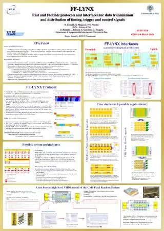
FF-LYNX Fast and Flexible protocols and interfaces for data transmission and distribution of timing, trigger and control signals R. Castaldi, G. Magazzù, P. G. Verdini INFN – Sezione di Pisa G. Bianchi, L. Fanucci, S. Saponara, C. Tongiani Dipartimento di Ingegneria della Informazione - Università di Pisa ACES 2009 CERN 3-4 March 2009 Project funded by INFN V Commission Overview FF-LYNX Interfaces a possible conceptual architecture • Genesis of the FF-LYNX Project • • Similar requirements in future High Energy Physics (HEP) experiments on distribution of Timing, Trigger and Control (TTC) signals and Data Acquisition (DAQ) w. r. t. trigger latency, bandwidth, flexibility, radiation hardness, power dissipation and robustness against component failures. • • Existing competences at INFN and DII-IET in design of complex digital ASICs, radiation tolerant ICs and communication protocols and interfaces for HEP and space applications. • Project phases and targets • 1. Analysis of the requirements for data transmission in HEP experiments (CMS Pixel and Strip Detectors, Atlas, ...) and review of existing communication protocols for space (SpaceWire, FiberWire,...) and conventional (Ethernet, FireWire,…) applications.2. Development of software models of current readout systems, to be used as test bench for next phases.3. Definition of a custom communication protocol granting the target requirements: • integrated distribution of TTC signals with controlled trigger latency and handling of DAQ processes. • error robustness of critical data (trigger and sync patterns). • flexibility w. r. t. different parameters (data rate, data format, ...) and architectures. • 4. Validation and performance evaluation of the defined protocol through system and link simulation (Simulink, C++, VHDL, ...).5. Design of interfaces that implement the protocol and of data concentrator blocks; design and production of test ICs; electrical and radiation tests.6. Final target: fully characterized IP cores and VHDL models of designed blocks. Uplink Downlink Blocks/functions in dashed line are selectable. Blocks in red already have a functional VHDL model. Example: DL_RX Synchronizer: synchronizes the RX on the THS channel, reconstructing the 40 MHz line clock: Internal block diagram Functional model simulation FF-LYNX Protocol • Integration of TTC and DAQ transmission in the same packed based protocol. • Flexibility w.r.t. different system architectures and data formats. • Downlink (DL_TX and DL_RX interfaces) • Transmission of clock, triggers (high priority commands), frames (low priority data and commands) on 2 lines (CLK & DAT). • Link speed 160 Mbps or 320 Mbps → 4 or 8 bits in each 40 MHz clock cycle, divided in a THS (Trigger, Header, Sync) channel (2 bits) and a FRM (frame) channel. • Trigger command and header pattern (marking the beginning of a frame) transmitted in the THS channel in a 6 bits, bit flip tolerant encoding. TRG are sent always with highest priority, HDR are scheduled for transmission when the THS channel is free from TRG transmissions. • The RX interface uses TRG, HDR and possibly other SYNC sequences to keep itself synchronized with the 40 MHz clock of THS channel. • Uplink (UL_TX and UL_RX interfaces) • Transmission of frames, optionally tagged with a label for event building purposes. • Two lines (CLK & DAT) or single line (Data + Clock encoding); four possible link speed values (80, 160, 320, 640 Mbps). • Only the FRM channel in the DAT stream, typically carrying readout data from front end chips. The 6-bit frame header (HDR) marks the beginning of a frame. • Transparent link concept: frames can carry any type of payload sync reached sync has been lost sync recovered Case studies and possible applications A possible downlink data stream Current architecture: “standard” CMS TTC distribution with “fast” I2C controls and token based analogue readout.Architecture proposed for the Phase I upgrade: “standard” CMS TTC distribution with “fast” I2C control and custom token based protocol for the digital readout 2160 Mbps optical fibers available for DAQ. Downlink frame structure Uplink frame structure • →Flexibility w.r.t. transmitted data/commands: for example a 3 byte I2C command can be carried. Possible module and detector architecture for the Phase II upgrade of the Strip Tracker (with no trigger data readout): daisy chains of Front-End ASICs within the modules and, optionally, daisy chain of modules. Expected data rate for raw data, at r = 78 cm: 5 Mbps/FE chip 40 Mbps/module. “Hybrid” architecture for the Phase I upgrade: FF-LYNX based TTC distribution, custom token based digital readout within the module and FF-LYNX based digital readout from the TBM 4 160 Mbps optical fibers available for DAQ. A possible frame payload: 3 byte I2C command CMS Pixels: Phase I and Phase II upgrades CMS Strips: Phase II upgrade Possible system architectures Star topology Down-Link: a DL_TX and DL_RX pair between each Front-End chip and a Data Concentrator device, delivering triggers, clock and data/commands to the FE chip. Up-Link: a UL_TX and UL_RX pair between each FE chip and the DC transferring DAQ/command response data; a DCM block inside the DC merges data streams from different sources and optionally performs event building. FF-LYNX based architecture for the Phase I upgrade: FF-LYNX based TTC distribution and DAQ with trigger based individual ROC readout 4 160 Mbps optical fibers available for DAQ and reduced latency of readout data w.r.t. triggers. Expected data rates for Phase I (inner layer): 40 Mbps from each ROC, 6÷16 hit ROCs/module 240 ÷ 640 Mbps from each module (16 ROCs). • Ring topology (with redundant links) • Modified protocol with no distinction between Down-Link and Up-Link. • Triggers propagate along the chain with the highest priority (on dedicated THS channel). • Each node handles the transmission of data frames generated locally or by previous nodes. • Distributed data concentration/event building functions. • Redundancy against non-contiguous node failures: 2 selectable, equivalent ports in each RX and TX interface. Possible module and detector architecture for the Phase II upgrade of the Strip Tracker (with trigger data readout and embedded trigger processors): data concentrators in the modules and high speed links between modules and trigger processors.Expected data rate for trigger data, at r = 78 cm: 120 Mbps/FE chip 960 Mbps/module. FF-LYNX based architecture for the Phase II upgrade: two 640 Mbps electrical links from each ROC; two uplink optical fiber (≥ 1.6 Gbps) for each 4-ROC module and one downlink optical fiber optionally shared among several modules. Expected data rates for Phase II (inner layer): 800 Mbps from each ROC, up to 3.2 Gbps from each module (4 ROCs). A test bench: high-level VHDL model of the CMS Pixel Readout System Output: “Readout file” listing readout data in a simple custom text format. Example: [Event number] [1st Hit Data]...[last Hit Data] [Status byte] ; Input: “Hit file” describing hit pixel addresses and amplitudes in a simple custom text format. Example: [Time index] – [L1T] – [1st Hit Data] ... [last Hit Data] ; where [Hit Data] = ( [ROC num] , [column addr (DC number)] , [row addr] , [hit ampl] ) Functional simulations: VHDL models of FF-LYNX interfaces will be included in the CMS Pixel readout system model for an overall functionality verification and performance evaluation. Importance of high level system simulations as a first, fundamental verification step of the design flow. Trigger validation of hits and DC readout mode setting Hit receiving by PUCs and column drain in a DC ROCs’ readout cycle starting by TBM ROCs’ readout cycle starting by TBM