Download
1 / 20
210 likes | 230 Views
Explore the physics modeling abilities with STAR-CD for detailed 1-D models of aftertreatment systems, covering flow characteristics, chemical kinetics, heat transfer, soot filtration, and more. Learn about representative channel coupling and coupling algorithms for accurate simulations.

E N D
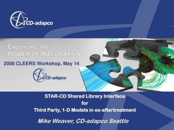
2008 CLEERS Workshop, May 14 STAR-CD Shared Library Interface for Third Party, 1-D Models in es-aftertreatment Mike Weaver, CD-adapco Seattle
Outline • Overview of es-aftertreatment- Analysis methodology and physics- Modeling abilities and examples • 1-D Model Interface- Physics- Modeling and Use
AFTERTREATMENT MODELING GOALS • Physical Mechanisms Included: • Flow characteristics in individual monolith channels • Global flow characteristics upstream/downstream of monolith (eg. expansion/contraction of exhaust tube) • Chemical Kinetics: Catalytic surface reactions and gas phase chemistry using DARS • Solid/Fluid heat transfer of the entire system • Soot Filtration Model for DPF • Temporal and 3D spatial variation upstream due to the Aftertreatment Device
Representative Channel Coupling • Velocity, pressure, and all other flow variables are continuously coupled with a coupling algorithm in STAR-CD (connect average) • Coupling insures average flux continuity across discrete pairs of boundary regions • In this example, each channel is associated with a different radial zone of the inlet and outlet manifold
REPRESENTATIVE CHANNEL COUPLING • Cartesian Based Subdivision • Automatic subdivision/coupling from user supplied model
REPRESENTATIVE CHANNEL COUPLING • User Supplied Subdivision
Conjugate Heat Transfer Coupling z T = T (z) q = q (z)
SIMPLE TransientSolver for Multiple Time Scale Physics • Multiple Time Scale Physics • Conduction heat redistribution time on order 10’s minutes • Catalyst adsorption/desorption time on order of minutes • Thermal warm-up/light-off time on order of minutes • Fluid channel resident time on order of 10-100ms • Chemical equilibrium time on order of 1ms • Fluid & chemistry is in a quasi-steady state relative to the warm-up, adsorption, and heat diffusion time scale • SIMPLE transient with DARS Coupling • Completely implicit, stable at any time step size • Stable for time steps on the thermal time scale and yet accurate representation of the fluid and chemistry quasi-steady states • >1000 fold increase in performance over PISO
Example: SELECTIVE CATALYTIC REDUCTION (SCR) AMMONIA MASSPERCENT • Injection captured with STAR-CD’S Lagrangian spray model • Composition modeled with STAR-CD’s multi-component spray feature • Thermolysis and hydrolysis of urea can also be treated: WATER MASSPERCENT CO(NH2)2 NH3 + HNCO HNCO + H2O NH3 + CO2 WATER SPRAY TRAJECTORIES
SELECTIVE CATALYTIC REDUCTION (SCR) WITH SOME MECHANISM MODIFICATIONS, NO2 CONVERSION CAN ALSO BE PREDICTED... NH3 MASSFRACTION NO MASSFRACTION NO2 MASSFRACTION • NOTE: IMAGES ARE SHOWN GREATLY FORESHORTENED ACTUAL L/D OF TUBE IS ~100:1.
Surface Methane OxiCatalyst Mechanismin an Aftertreatment Device Device light-off near centerline Device warm-up Heat radial conduction redistribution Mid-channel light-off Continued heat redistribution OD channel light-off Approach steady-state Temperature contours (°C)
Loaded filter soot mass density • uneven distribution of the collected soot within the DPF • strong lateral variations • somewhat weaker axial variations with more soot downstream
Exit from Turbine Flexible Coupling 90° bend DOC DPF Complete Systems with Multiple Devices Loading Thermal warm-up, light-off and regeneration Heat losses on piping SiC DPF, Corderite DOC each with 30 representative channels Non-catalyzed soot filter Model compared to well instrumented experiments
Warm-up and Regeneration - Temperature DPF t=25s t=300s DOC t=75s t=500s t=150s t=1000s
Catalyst 1 Diesel-particulate filter Pipes Catalyst 2 Exhaust manifold + Turbo charger Pipes + Absorbing ducts Complete Systems with Multiple Devices
STAR-CD applies Porous Coefficients to match pressure drop returned by 1-D Model (each channel) 1-D Model to STAR-CD Channel Outlet Boundary (each channel): ! Temperature ! Pressure ! Transported Scalar Concentrations Solid Enthalpy Solution Along Channel STAR-CD to 1-D Model (z position) each channel Channel Inlet Boundary (each channel): From 1-D Model to STAR-CD ! ! Mass Flow Rate Wall Heat transfer to solid, Q(z) ! ! Temperature Heat Capacity and enthalpy ! Pressure Cp(z) and h(z) ! ! Transported Scalar Concentrations Thermal Conductivities: K_axial(z), K_radial(z) Solid Temperature Solution Along Channel Axis, (z position) each channel From STAR-CD to 1-D Model ! Solid temperature, T(z) 1-D Model Physics STAR-CD Solid Temperature Solution
es-aftertreatment Modelingfor 1-D Models: Scalars and Storage • Transported Scalars: All reactants and products that are transported in the flow are defined as transported scalars in Prostar and given inlet boundary concentrations for the model. • Post processing: of transported scalar concentrations is available over the flow and over the device volume. • Non-transported Scalars: 1-D models additionally may define any number of non-transported scalars, independent of Prostar, through the esafter1d interface. STAR-CD provides and efficiently manages cell storage for this data for restarts as well as distribution in parallel processing. These are also available for post processing over the volume of the device they apply to. • Arbitrary Device and Channel Memory Storage: In addition to cell-wise storage, STAR-CD provides and manages additional memory per device and per channel.
es-aftertreatment Modelingfor 1-D Models: Prostar Definition
es-aftertreatment Interface for Third Party 1-D Models: Concluding Points • Benefit from established, advanced, calibrated reaction models developed at universities and research laboratories with a specific focus on aftertreatment • Couples Star flow and thermal solution with 1-D kinetics • Can use multiple vendor 1-D models in a single simulation with multiple devices. • Interface accommodates either cell discretization or vertex discretization in the 1-D model. • Present Vendors Providing libraries for STAR-CD 1-D interface: - axi-suite, Exothermia (Affiliated with Aristotle University, Thessaloniki)- XMR (Affiliated with the Institute of Chemical Technology, Prague)