Conversion and Reactor Sizing
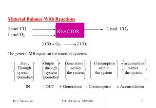
Conversion and Reactor Sizing. Lec 5 week 6. Definition of Conversion for the following reaction. The reaction can be arranged as follows:

Conversion and Reactor Sizing
E N D
Presentation Transcript
Conversion and Reactor Sizing Lec5 week 6
Definition of Conversionfor the following reaction • The reaction can be arranged as follows: • Now we ask such questions as "How can we quantify how far the above reaction proceeds to the right?" or “How many moles of C are formed for every mole A consumed? • A convenient way to answer these questions is to define a parameter called conversion. • The conversion XA is the number of moles of A that have reacted per mole of A fed to the system.
Batch Reactor Design Equations in terms of conversion • In most batch reactors. the longer a reactant stays in the reactor, the more the reactant is converted to product until either equilibrium is reached or the reactant is exhausted, Consequently. in batch systems the conversion X is a function of the time the reactants spend in the reactor. • If NAO is the number of moles of A initially in the reactor then the total number of moles of A that have reacted after a time t is [NA0 *X]
Batch Reactor Design Equations in terms of conversion • the mole balance on species A for a batch system is given by the following equation: • reactant A is disappearing: therefore, we multiply both sides of Equation by -1 then
Batch Reactor Design Equations in terms of conversion • For batch reactors. we are interested in determining how long to leave the reactants in the reactor to achieve a certain conversion X. To determine this length of time, we write the mole balance. Equation in terms of conversion. NA=NA0(1-XA) • by differentiating the above equation with respect to time, remembering that NAo is the number of moles of A initially present and is therefore a constant with respect to time.
Batch Reactor Design Equations in terms of conversion To determine the time to achieve a specified conversion X This equation is now integrated with the limits that the reaction begins at time equal zero where there is no conversion initially (i.e., t = 0, X = 0).
Design Equations for Flow Reactors • For a batch reactor. we saw that conversion increases with time spent in the reactor. For continuous-flow systems, this time usually increases with reactor volume. E.g. the bigger /longer the reactor, the more time it will take the reactants to flow completely through the reactor and thus, the more time to react. • The conversion X is a Function of reactor volume V. • If FA0is the molar flow rate of species A fed to a system operated at steady state. The molar rate at which species A is reacting within the entire system will be FA0X.
Design Equations for Flow Reactors • For liquid systems, CA0, is commonly given in terms of molarities, for example, CAO = 2 moll/dm3. • For gas systems, CAo can be calculated from the entering temperature and pressure using the Ideal gas law.
Example(1 ) • A gas of pure A at 830 kPa (8.2 atm) enters a reactor with a volumetric flow rate,v0 of 2 dm3/s. at 500 K. Calculate the entering concentration of A, CA0, and the entering molar flow rate. FAo.
solution • For flow reactors (CSTR) For gas phase reactor.
Tubular Flow Reactor (PFR) For a flow system, FA has previously been given in terms of the entering molar flow rare FA0 and the conversion X By differentiate Substitute in the 1st equation to give the differential form of the design equation for a plug-flow reactor (PFR): We now separate the variables and integrate with the limits V = 0 when X = 0 to obtain the plug-flow reactor volume necessary to achieve a specified conversion X:
Example • Consider the liquid phase reaction which we will write symbolically as • A B • The first order (-rA = k CA) reaction is carried out in a tubular reactor in which the volumetric flow rate, v, Is constant i.e. v =v0. • (a) Derive an equation relating the reactor volume to the, entering and exiting concentrations of A the rate constant k, and the volumetric flow rate v. • (b) Determine the reactor volume necessary to reduce the exiting concentration to 10% of the entering concentration when the volumetric flow rate is I0(dm3/min) and the specific reaction rate, k. is 0.23 min-1 .