Download
1 / 27
270 likes | 496 Views
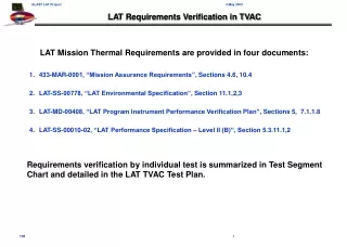
LAT Transport Container TVAC Facility Modifications Design Status 7 October 2005. Paul Dizon Ray Suziedelis. Current Status. LAT Transport Container Weldment drawings for Sub-Floor and Load Frame out for bid Analysis shows positive margins of safety for transportation and handling loads

E N D
LAT Transport Container TVAC Facility Modifications Design Status 7 October 2005 Paul Dizon Ray Suziedelis
Current Status • LAT Transport Container • Weldment drawings for Sub-Floor and Load Frame out for bid • Analysis shows positive margins of safety for transportation and handling loads • Subfloor suitable to withstand 6.0g, 3.5g, 2.0g truck loads • Load Frame sized for 3.0g ,1.7g ,3.2g enveloped transport loads as follows:
Current Status - Cont’d • TVAC Rail Support Structure • Piece-part and sub-assembly drawings currently in review • Assembly drawing in progress • Analysis shows positive margins of safety • TVAC Table • Piece-part drawings currently in review • Assembly drawing in progress • Analysis shows positive margins of safety • TVAC Cart • Piece-part and assembly drawings currently in review • Analysis shows positive margins of safety
LAT Transport Container - Analysis Methodology • Shipping Container treated as protective enclosure, not as primary structure • Load Frame and Sub-Floor act as primary structure carrying load of LAT • Assume applied environmental load occurs simultaneously in all three axes • FEA Model and Hand Calculations used to determine loads and/or stresses in the following • Load Frame • Sub-Floor • Interface Plate • Bolted Joints • Welded Joints
LAT Transport Container - Analysis Criteria • Design Limit Loads (per LAT-SS-06640) • Axial + 6.0 g • Longitudinal + 2.0 g • Lateral + 3.5 g • Mass Properties of Payload • Mass 6750 lbs, MAX • CG (0 in, 0 in, 24 in) from Interface Plate • Factors of Safety • Yield & Local Instability: FS = 3.0 • Ultimate & Buckling: FS = 5.0 • Structural Margins of Safety Must be Positive • Rotation of Interface Plate at LAT Interface (Line of Action) + 1.0 deg • Maintain Static and Dynamic Clearance Between Payload and Container
LAT Transport Container - FEM Includes SLAC-provided LAT FEM 9314 Nodes, 9711 Elements
TVAC Facility Modifications - Analysis Methodology • FEA Model used to determine loads and stresses in • TVAC Rail Support Structure • TVAC Table • TVAC Cart • Hand Calculations used to determine margins for • Bolted Joints • Welded Connections • Stability
TVAC Facility Modifications - Analysis Criteria • Mass Properties of LAT Test Article • Mass 13,000 lbs, MAX • CG from Floor (0 in, 0 in, 136.35 in) • CG from to surface of Table (0 in, 0 in, 64.38 in) • Factors of Safety • Yield & Local Instability FS = 3.0 • Ultimate & Buckling FS = 5.0 • Margins of Safety – Must be Positive
TVAC Rail Support Structure – FEM Two rails: Angle-Capped, Plate-Capped Three tables: 5’x10’ / 10’x10’ / 5’x10’ (do not rigidize rails) 94002 Nodes, 65896 Elements
TVAC Rail Support, Chamber Structure – Margins of Safety, Cont’d
TVAC Table and Cart – FEM • 3835 Nodes, 4222 Elements • 13000 lb LAT/Fixture on Table • Fore-, Centered-, and Aft-Table Positions Examined
Proof Load Discussion • LAT Transport Container • Sub-Floor • Fork-Lift Configuration • Axial Load: 2x worst-case vertical load [(6750 lbs + Load Frame mass) x 2.0 g] • Support through Fork-Lift Tubes on tine simulators • Tie-Down Configuration • Tie-Down Load (2x worst-case, function of strap angle) • Support Subfloor on T-slotted floor in Test Facility • Load Frame • Flight Configuration • Axial Load: 2x (6750 lbs x 3.2 g), bypassing wire rope isolators • Load Applied at LAT flexure interface into Load Frame with Sub-Floor Resting on Ground • TVAC Rail Support Structure • Tested as a full-up assembly • Axial Load: 2x (13,000 lbs x 1.0 g) / 0.94 (0.94 = factor for temperature effects on material, @ 55C) • Load supported by 10’x10’ TVAC Table, slowly rolled down and back, full-length of rails • TVAC Table and Cart • Tested as a full-up assembly • Axial Load: 2x (13.000 lbs x 1.0 g) • Load supported by 10’x10’ TVAC Table, fore, aft and center positions of rails
Conclusions • Detailed stress analysis still ongoing. • Latch design for LAT Transport Container • Winch details for TVAC Facility • Tug lug details for TVAC Cart • Detailed review of mechanical joints and welded connections. • Known margins provide sufficient confidence to allow production of primary structures • LAT Transport Container Sub-Floor Weldment • LAT Transport Container Load Frame Weldment • TVAC Rail Support Structure Weldments • TVAC Cart Weldment • TVAC Table Caster Mounts
Transportation Load Factors NOTES: • NASA -7005 Load expressed as limit load, derived from NASA SP-8057, Structural Design Criteria Applicable to a Space Shuttle which specifies limit load factors shall be applied at the support points of the transporting vehicle • NASA SP-8007 3.0 g peak from composite loadbed inputs (Fig 2). Curve envelops maximum reported vertical accelerations measured on cargo floor for all types of commerical vehicles traveling normal routes. Does not include interaction between cargo and transport. • NASA SP-80073.2 g peak 0-2.5 Hz band, 3.85% probability of occurance for tractor-trailer loadbed, 98.5% probability of peak loads equal to or lower than 3.2 g. Representative samples of loads measured on cargo floor of the vehicle for various road conditions, vehicle speeds in typical transcontinental trip. • MIL-STD-810F Category 4 Truck/trailer/tracked restrained cargo. Data measured at cargo floor of seven different configurations of truck and semitrailer combinations. Bother conventional and air-cushioned suspensions are represented. Data collected from typical interstate highways with rough portions as part of database.
Excerpt From NASA 7005 8.1 Low Frequency Vibration and Transient Responses. The designer of aerospace vehicle structures and hardware must carefully consider all the loads and environments outlined in prior sections, especially Sections 4 through 7. How design criteria are integrated into the design process is often determined by the particular phase (early, interim, or late) of the vehicle or hardware design process. As illustrated in Figures 8.1 and 5.1, the design process is almost always iterative [8.1, 8.2], using a team approach required to achieve a weight-efficient and cost-effective design. Thus design and test criteria usually change as the design progresses. Most organizations intentionally use higher design margins initially when each load is considered separately, and then reduce them to minimum acceptable values later when various loads are considered in combination and/or sequence. Other organizations use alternative procedures to achieve system design goals. Transportation and handling loads, which are normally bounded by the limit load factors given in Table 8.1 [8.3], must also be included unless special protection is provided to assure that they contribute negligible damagecompared to flight loads. The following subsections summarize design margins, followed by a discussion of each end of the design process, namely, preliminary and early design, and late and final design. Lastly, test criteria and their relationship to design criteria are addressed.
MIL-STD-810F DoD Test Method StandardFor Environmental Engineering Considerations and Laboratory Tests Excerpts From Method 514.5 Vibration - Annex A Tailoring Guidance For Vibration Exposure Definition, Section 2.2 Transportation 2.2.1 Category 4 - Truck/trailer/tracked - restrained cargo. These transportation environments are characterized by broadband vibration resulting from the interaction of vehicle suspension and structures with road and surface discontinuities. Representative conditions experienced on moving materiel from point of manufacture to end-use are depicted in Part One, figure 4-2. This environment may be divided into two phases, truck transportation over U.S. highways and mission/field transportation. Mission/field transportation is further broken down into two-wheeled trailer/wheeled vehicles and tracked vehicle categories. • Truck transportation over U. S. highways. This involves movement from the manufacturer’s plant to any continental United States storage or user installation. (Data are available for U.S. roads but not for roads in other countries.) This movement is usually accomplished by large truck and/or tractor-trailer combination. Mileage for this transportation generally ranges from 3200 to 6400 kilometers (2000 to4000 miles) over improved or paved highways. 2.2.1.c Exposure Levels (1) Truck transportation over U. S. highways. Derive exposure levels from Annex C, figure 514.5C-1.These figures are based upon data measured at the cargo floor of seven different configurations of trucks and semitrailer combinations. Both conventional suspensions and air-cushioned suspensions are represented. The data were collected from typical interstate highways with rough portions as part of the database.
NASA SP-8077Transportation and Handling Loads • Excerpt From Section 2.2.2 - Inputs From Loadbed Measurements • Subsection 2.2.2.1 – Inputs Road Transport Loadbed Inputs
Vertical Acceleration (0-peak), g’s Figure 2. Transport vehicle composite loadbed data Vertical Accelerations Road Transport Loadbed InputsNASA SP-8077
NASA SP-8057Structural Design Criteria Applicable to a Space Shuttle • Original Source of 6.0g Limit Load dated March 1972 • Document Applicable to Manned Space Shuttle Missions • Transportation Load Factors Specified For Components