Download
1 / 91
910 likes | 928 Views
This resource provides a comprehensive guide to understanding circuits, including the concepts of resistance, voltage, and current. It covers both series and parallel circuits and includes exercises for students to practice their understanding.

E N D
Physics of Circuits Created for BW Physics Middle School Science Teachers By Dick Heckathorn 23 April 2K + 8
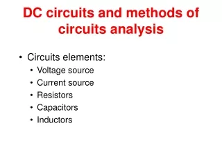
A Resistor V Ammeter Voltmeter Battery Equipment with Schematic Symbols • 1. Meters • 2. Resistors • 3. Battery • 4. Connecting Wire • 5. Connecting Wire with Clips
Voltmeter Ammeter with leads connected
Meter Connections • Current VoltageResistance Common Jack Black Lead
Units • Current (amp) charge/time • Voltage (Volts) energy/time • Resistance (ohm) opposition
A. Finding Total or Equivalent Resistanceof resistors connectedinSeries
R1 R3 R2 • 1. Measure and record the resistance of three resistors. _______ _______ _______
_______ _______ R1 + R2 R1 + R3 R2 + R _______ • 2. Connect two of the resistors end to end (in series) and measure the resistance across each pair.
3. A new resistor equal to the sum of the two resistors can replace the two resistors in a circuit. It will have the same effect in a circuit as the two resistors. • We call the sum, an equivalent resistance or a total resistance.
R1 + R2 • 4. Develop a rule from which you can predict the equivalent resistance of two resistors in series. R1 + R3 R2 + R3
R1 + R2 + R3 • 5. Connect all three resistors end to end and measure the resistance across all three. _____________
6. Does your rule for three resistors connected in series the same as for two resistors connected in series? • Yes ___ No ___
7. Your instructor hopes that you found the following to be true. Remember this is for ONLY resistors in series!
B. Finding Total or Equivalent Resistance of Resistors in Parallel
R2 R3 _________ _________ _________ R1 • 1. Record the resistance of the three resistors that you measured before.
R1 : R2 R2 : R3 _________ _________ _________ R1 : R3 • 2. Connect two of the resistors as shown (in parallel) and measure the resistance across each end.
3. Develop a rule from which can predict the equivalent resistance of two resistors in parallel?
R1 : R2 : R3 ____________ • 4. Connect all three resistors as shown, then measure the resistance across all three.
Carry Electrical Problem • Homework Assignment • NDSL http://nsdl.org/
5. Is the rule for finding the equivalent resistance of three resistors connected in parallel the same for finding the equivalent resistance of two resistors connected in parallel? • Yes ___ No ___
6. The rule is: Remember this is ONLY for resistors in parallel!
A 1. Measure the value of a resistor. R = ___ Next construct the following circuit. Now, set the ammeter to 10 amp. Finally complete the curcuit. R
A Resistor with Amp Meter Circuit R
A VA VR VB Measure and record: I R Voltage VA Voltage VB Current I Voltage VR
Measuring Voltge of Battery A VB I R I? VB = ________ 32
Measuring Voltage across R A VR I R VR = ________ 33
A VA VR VB Measuring Voltage across Meter I R VA = ________
Conclusion(s) A VA VR VB I R VB,I,andR? Compare VBwithVA and VR 35
6. Divide the voltage (VB) by the resistance (R). 7. How does VB/R compare to the measured current? Be sure to keep track of units.
VR VB 8. Remove Ammeter R
VR VB 9. Connect and measure the voltage across the battery and then the resistor. Record the values. R VR = _______ VB = _______
VR VB Conclusion(s)? R How do VB and VR compare?
10. Calculate: This is the same as the ___________.
11. What does your instructor say about this? • Your instructor says that VBand VRshould be the same as the energy per charge given to the electrons by the battery VB and then removed by the resistor VR.
A 1. Measure the value of two resistors. R1 = _________ R2 = _________ Then construct the following circuit. R1 R2
A Batt+A+2 R in Series R1 R2
A R1 R2 2. Measure and record the current. I = ____________
A VB V1 V2 3. Measure and record the voltage across the battery and both of the resistances. I R1 R2 VR2 = _______ VR1 = _______ VB = _______
4. How does VB compare to VR1 and VR2? • 5. Calculate VR1/R1 and VR2/R2 • ______ ______ • What do these values compare to?
5. Calculate both VR1/R1 and VR2/R2. How do they compare? Are Equal? Yes What do these values compare to? Current? Yes