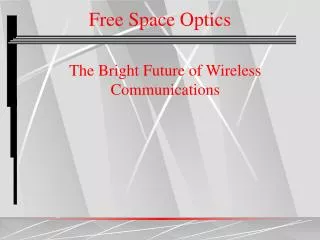
FREE SPACE OPTIC COMMUNICATIONS
FREE SPACE OPTIC COMMUNICATIONS. Presented By: Ankur S. Sharma Course: ECEE-641 Fiber Optics and Optical Communications I Instructor: Dr. Timothy P. Kurzweg. PRESENTATION LAYOUT:. Introduction to the concepts of Free Space Optics (FSO). Propagation concepts, Link Budget calculations.

FREE SPACE OPTIC COMMUNICATIONS
E N D
Presentation Transcript
FREE SPACE OPTIC COMMUNICATIONS • Presented By: Ankur S. Sharma • Course: ECEE-641 Fiber Optics and Optical Communications I • Instructor: Dr. Timothy P. Kurzweg
PRESENTATION LAYOUT: • Introduction to the concepts of Free Space Optics (FSO). • Propagation concepts, Link Budget calculations. • FSO: Last Mile Bottleneck Solution. • Configurations of FSO systems. • Chaining in FSO Systems • DATA security/ Safety considerations for FSO systems. • Signal Propagation impediments. • Advantages of FSO as regards to other widely used systems. • Physical Applications of FSO systems • Manufacturers/Players in field of FSO.
Requirements of a good Transmission System: • High Bandwidth • High BER • Low SNR • Power efficient • Provide Data Security. • Low cost • Easy to install and maintain.
Introduction to the concepts of Free Space Optics (FSO) • FSO is a line-of-sight technology which uses LASERS and Photo detectors to provide optical connections between two points—without the fiber. • FSO can transmit data, voice or video at speeds capable of reaching 2.5 Gbps. Products capable of speeds upto 10 Gbps are expected to hit the markets within one year. • FSO units consist of an optical transceiver with a laser (transmitter) and a Photo detector (receiver) to provide full duplex (bi-directional) capability. • FSO systems use invisible infrared laser light wavelengths in the 750nm to 1550nm range.
Free Space Optic Link Equation: • • Preceived = received power • • Ptransmit = transmit power • • Areceiver = receiver area • • Div = beam divergence (in radians) • • Range = link length
LAST MILE BOTTLENECKS • Less then 5% of all buildings in the US have a direct connection to the very high speed (2.5-10 Gbps) fiber optic backbone, yet more than 75% of businesses are within 1 mile of the fiber backbone. • Most of these businesses are running some high speed data network within their building, such as fast Ethernet (100 Mbps), or Gigabit Ethernet (1.0 Gbps). • Yet, their Internet access is only provided by much lower bandwidth technologies available though the existing copper wire infrastructure (T-1 (1.5 Mbps), cable modem (5 Mbps shared) DSL (6 Mbps one way) ), etc. • The last mile problem is to connect the high bandwidth from the fiber optic backbone to all of the businesses with high bandwidth networks.
DSL and cable modems cannot provide true broadband services. Cable modems enjoy higher capacity, yet the channel is shared and the amount of bandwidth at any given time is not guaranteed. Copper lines provide data rates to a fraction of 1 Mbps. T1 lines can reach upto a few Mbps but are still far away from the Gbps speed which the fiber backbone can support. The chart below shows how these technologies address different market segments based on technology, technical capabilities (reach, bandwidth), and economic realities.
A high-bandwidth cost-effective solution to the last mile problem is to use free-space laser communication (also known as or optical wireless) in a mesh architecture to get the high bandwidth quickly to the customers.
DATA SECURITY To overcome the security in a network two conditions are necessary: • (1) Intercept enough of the signal to reconstruct data packets and • (2) Be able to decode that information.
Preventing Interception of the SignalDirectional transmission:Narrow divergence of the FSO transmit path (shown in red) as compared to a typical Radio Frequency (RF) path (shown in blue). The tightly collimated FSO beam ensures that the signal energy is focused on the receiving unit, making interception of the beam extremely difficult.
Another view of the narrow beam divergence inherent in FSO transmission. (For clarity only one transit beam is shown.)
Signal Propagation Impediments: • Fog: The major challenge to FSO communications is fog. The primary way to counter fog when deploying FSO is through a network design that shortens FSO link distances and adds network redundancies. FSO installations in foggy cities such as San Francisco have successfully achieved carrier-class reliability. • Absorption: Absorption occurs when suspended water molecules in the terrestrial atmosphere extinguish photons. This causes a decrease in the power density (attenuation) of the FSO beam and directly affects the availability of a system. • Scattering: Scattering is caused when the wavelength collides with the scatterer. The physical size of the scatterer determines the type of scattering. When the scatterer is smaller than the wavelength, this is known as Rayleigh scattering. When the scatterer is of comparable size to the wavelength, this is known as Mie scattering. • Physical obstructions: Flying birds can temporarily block a single beam, but this tends to cause only short interruptions, and transmissions are easily and automatically resumed. • Building sway/seismic activity: The movement of buildings can upset receiver and transmitter alignment. • Safety: To those unfamiliar with FSO, safety is often a concern because the technology uses lasers for transmission. • Scintillation: Heated air rising from the earth or man-made devices such as heating ducts creates temperature variations among different air pockets. This can cause fluctuations in signal amplitude which leads to image fluctuations at the FSO receiver end.
Rough Estimate of Power losses in the system Infrared ight (765 nm) : Clear, still air -1 dB/km -5 dB/km Scintillation 0 to -3 dB/km 0 Birds or foliage Impenetrable 0 to -20 dB Window (double-glazed) -3 dB -1 dB Light mist (visibility 400m) -25 dB/km -1 dB/km Medium fog (visibility 100m) -120 dB/km -1 dB/km Thick fog (visibility 40m) -300 dB/km -1 dB/km Light rain (25mm/hour) -10 dB/km -10 dB/km Heavy rain (150mm/hour) -25 dB/km -40 dB/km
ADVANTAGES OF FSO SYSTEMS No licensing required. Installation cost is very low as compared to laying Fiber. No sunk costs. No capital overhangs. Highly secure transmission possible. High data rates, upto 2.5 Gbps at present and 10 Gbps in the near future.
Applications Of FSO Systems Disaster management as was exhibited during the Sept 11 attacks. Merill Lynch & Co. has set up FSO system from its Vesey Street office towers across the Hudson River to an alternate site in New Jersey. TeraBeam, a major producer of FSO equipment, successfully deployed FSO at the Sydney Summer Olympic Games. A network of FSO devices is fast coming up in Seattle which is touted as the Capital of Fog. Manufacturers believe that if an FSO system can successfully work in Seattle then it can do so in any part of the world. Affordably extend existing fiber network. Disaster recovery and temporary applications
Manufacturers/ Players in the Field of FSO: LightPointe: A San Diego based company which received contributions from Cisco Systems and Corning to the tune of $33 million. It has raised a total of $51.5 million. AirFiber: Another San Diego based company which has received contributions from Nortel Networks to the tune of $50 million. It has raised a total of $92.5 million. Terabeam: A Kirkland, WA based company has received funding from Luscent technologies to the tune of $450 million and has raised $585 million to date.