Download
1 / 38
410 likes | 469 Views
Learn about radio communication, propagation modes, antenna concepts, and more in wireless communication systems. Discover how antennas, polarization, and gain influence wireless transmission in this informative lecture.

E N D
EE4220 Communications system Radio Communication Dr. Hassan Yousif Electrical Engineering Department College of Engineering Salman Bin Abdulaziz University Lectno-6
What is Wireless Communication ? • Transmitting voice and data using electromagnetic waves in open space (atmosphere) • Electromagnetic waves • Travel at speed of light (c = 3x10⁸ m/s) • Has a frequency (f) and wavelength (l) • c = f x l • Higher frequency means higher energy photons • The higher the energy photon the more penetrating is the radiation
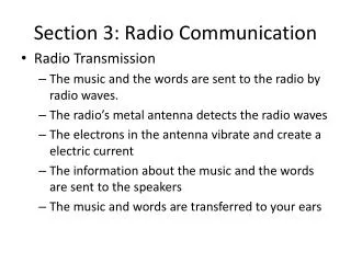
Radio Communication • Radio or radio communication means any transmission, emission, or reception of signs, signals, writing, images, sounds or intelligence of any nature by means of electromagnetic waves of frequencies lower than three thousand gigacycles per second (3000 GHz) propagated in space without artificial guide. • Examples of radio communication systems: • Radio broadcasting. • TV broadcasting. • Satellite communication. • Mobile Cellular Telephony. • Wireless LAN. • Multimedia communication & Mobile Internet [Slimane]
The Radio Spectrum • The frequency spectrum is a shared resource. • Radio propagation does not recognize geopolitical boundaries. • International cooperation and regulations are required for an efficient use of the radio spectrum. • The International Telecommunication Union (ITU) is an agency, within the UN, that takes care of this resource. • Frequency assignment. • Standardization. • Coordination and planning of the international telecommunication services. [Slimane]
Propagation modes • Radio propagationis the behavior of radio waves when they are transmitted, or propagated from one point on the Earth to another, or into various parts of the atmosphere. As a form of electromagnetic radiation, like light waves, radio waves are affected by the phenomena of • Reflection • Refraction • Diffraction • Absorption • Polarization and scattering
Fundamental Antenna Concepts • Reciprocity • Radiation Patterns • Isotropic Radiator • Gain • Polarization
Reciprocity • In general, the various properties of an antenna apply equally regardless of whether it is used for transmitting or receiving • Transmission/reception efficiency • Gain • Current and voltage distribution • Impedance
Radiation Patterns • Radiation pattern • Graphical representation of radiation properties of an antenna • Depicted as a two-dimensional cross section • Reception pattern • Receiving antenna’s equivalent to radiation pattern Figure 1. 3D Radiation Pattern.
The main beam is the region around the direction of maximum radiation (usually the region that is within 3 dB of the peak of the main beam). The main beam in Figure 2 is centered at 90 degrees. The sidelobes are smaller beams that are away from the main beam. These sidelobes are usually radiation in undesired directions which can never be completely eliminated. The sidelobes in Figure 2 occur at roughly 45 and 135 degrees. The Half Power Beamwidth (HPBW) is the angular separation in which the magnitude of the radiation pattern decrease by 50% (or -3 dB) from the peak of the main beam. Another commonly quoted beamwidth is the Null to Null Beamwidth. This is the angular separation from which the magnitude of the radiation pattern decreases to zero (negative infinity dB) away from the main beam. Finally, the Sidelobe Level is another important parameter used to characterize radiation patterns. The sidelobe level is the maximum value of the sidelobes (away from the main beam). Cell-tower Antenna Array. These Antenna Arrays are typically used in groups of 3 (2 receive antennas and 1 transmit antenna).
Antenna Gain • Antenna gain • Power output, in a particular direction, compared to that produced in any direction by an isotropic antenna • Effective area • Related to physical size and shape of the antenna
Antenna Gain (cont.) • Relationship between antenna gain and effective area • G antenna gain • Ae effective area • f carrier frequency • c speed of light (» 3 x 10⁸ m/s) • carrier wavelength
Antenna Gain (cont.) • An antenna with a G = 3dB improves over the isotropic antenna in that direction by 3dB or a factor of 2
Polarization • Defined as the orientation of the electric field (E-plane) of an electromagnetic wave • Types of polarization • Linear • Horizontal • Vertical • Circular
Polarization • Vertically Polarized Antenna • Electric field is perpendicular to the Earth’s surface • e.g., Broadcast tower for AM radio, “whip” antenna on an automobile • Horizontally Polarized Antenna • Electric field is parallel to the Earth’s surface • e.g., Television transmission (U.S.) • Circular Polarized Antenna • Wave radiates energy in both the horizontal and vertical planes and all planes in between
Types of Antennas • Isotropic antenna • Idealized • Radiates power equally in all directions • Omnidirectional • Dipole antennas • Half-wave dipole antenna • Hertz antenna • Quarter-wave vertical antenna • Marconi antenna • Parabolic Reflective Antenna
Propagation Modes • Ground-wave propagation • Sky-wave propagation • Line-of-sight propagation
Ground Wave Propagation • Follows contour of the earth • Can propagate considerable distances • Frequencies up to 2 MHz • Example • AM radio
Sky Wave Propagation • Signal reflected from ionized layer of atmosphere back down to earth • Signal can travel a number of hops, back and forth between ionosphere and earth’s surface • Reflection effect caused by refraction • Examples • Amateur radio • CB radio
Line-of-Sight Propagation • Transmitting and receiving antennas must be within line of sight • Refraction • Bending of microwaves by the atmosphere • Velocity of electromagnetic wave is a function of the density of the medium • When wave changes medium, speed changes • Wave bends at the boundary between mediums
Line-of-Sight Equations • Optical line of sight • Effective (or radio) line of sight • d = distance between antenna and horizon (km) • h = antenna height (m) • K = adjustment factor to account for refraction, rule of thumb K = 4/3
Line-of-Sight Equations • Maximum distance between two antennas for LOS propagation: • h1 = height of antenna one • h2 = height of antenna two
LOS Wireless Transmission Impairments • Attenuation and attenuation distortion • Free space loss • Noise • Atmospheric absorption • Multipath • Refraction • Thermal noise
Attenuation • Strength of signal falls off with distance over transmission medium • Attenuation factors for unguided media: • Received signal must have sufficient strength so that circuitry in the receiver can interpret the signal • Signal must maintain a level sufficiently higher than noise to be received without error • Attenuation is greater at higher frequencies, causing distortion
Free Space Loss • Free space loss Ideal isotropic antenna • Pt = signal power at transmitting antenna • Pr = signal power at receiving antenna • = carrier wavelength • d = propagation distance between antennas • c = speed of light (» 3 x 10⁸ m/s) where d and are in the same units (e.g., meters)
Free Space Loss • Free space loss accounting for gain of other antennas • Gt = gain of transmitting antenna • Gr = gain of receiving antenna • At = effective area of transmitting antenna • Ar = effective area of receiving antenna
Categories of Noise • Thermal Noise • Intermodulation noise • Crosstalk • Impulse Noise
Noise Terminology • Intermodulation noise • Occurs if signals with different frequencies share the same medium • Crosstalk • Unwanted coupling between signal paths
Other Impairments • Atmospheric absorption • Water vapor and oxygen contribute to attenuation • Multipath • Obstacles reflect signals so that multiple copies with varying delays are received • Refraction • Bending of radio waves as they propagate through the atmosphere
Fading in Mobile Environment • Fading • Time variation of received signal power caused by changes in transmission medium or path(s)
Multipath Propagation (MP) • Reflection • Occurs when signal encounters a surface that is large relative to the wavelength of the signal • Diffraction • Occurs at the edge of an impenetrable body that is large compared to wavelength of radio wave • Scattering • Occurs when incoming signal hits an object whose size is in the order of the wavelength of the signal or less
The Effects of MP Propagation • Multiple copies of a signal may arrive at different phases • If phases add destructively, the signal level relative to noise declines, making detection more difficult • Known as Intersymbol Interference (ISI)
Types of Fading • Fast fading • Slow fading • Flat fading • Selective fading • Rayleigh fading • Rician fading
Fading Source: Prakash Agrawal, D., Zeng, Q., “Introduction to Wireless and Mobile Systems,” Brooks/Cole-Thompson Learning, 2003 .