Download
1 / 10
180 likes | 411 Views
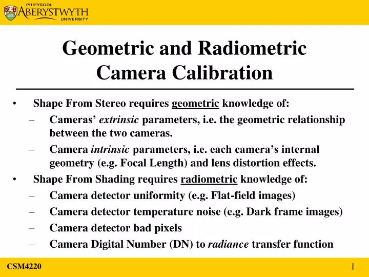
CSM4220. Geometric and Radiometric Camera Calibration. Shape From Stereo requires geometric knowledge of: Cameras’ extrinsic parameters, i.e. the geometric relationship between the two cameras.

E N D
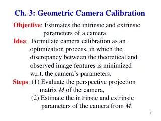
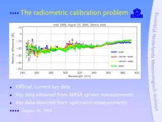
CSM4220 Geometric and RadiometricCamera Calibration • Shape From Stereo requires geometric knowledge of: • Cameras’ extrinsic parameters, i.e. the geometric relationship between the two cameras. • Camera intrinsic parameters, i.e. each camera’s internal geometry (e.g. Focal Length) and lens distortion effects. • Shape From Shading requires radiometric knowledge of: • Camera detector uniformity (e.g. Flat-field images) • Camera detector temperature noise (e.g. Dark frame images) • Camera detector bad pixels • Camera Digital Number (DN) to radiance transfer function 1
Camera Geometric Calibration • This has been a computer vision research topic for many years (hence many papers) • There are a number of available software tools to assist with the calibration process • Examples include: • Matlab Camera Calibration Toolbox • Open CV Camera Calibration and 3D Reconstruction • These often require a geometric calibration target – often a 2D checkerboard 2 CSM4220
Right Camera Images Left Camera Images Stereo Vision – calibration A sequence of left and right camera images of a 16 × 16 square checker-board used as part of the intrinsic and extrinsic calibration procedure for the AU stereo WAC cameras. 3 CSM4220
Stereo Vision – extrinsic calibration Camera Baseline separation, and relative orientation 4 CSM4220
Stereo Vision – intrinsic calibration 5 CSM4220
Stereo Vision –image rectification Using the geometric calibration results, an image rectification algorithm is used to project two-or-more images onto a common image plane. It corrects image distortion by transforming the image into a standard coordinate system See Fusiello et al., A Compact algorithm for rectification of stereo pairs, Machine Vision Applications, 12, 16-22, 2000 Image rectification illustrates how image rectification simplifies the search space in stereo correlation matching. (Image courtesy Bart van Andel) 6 CSM4220
Right rectified image Left rectified image ←1024 768 ↓ Stereo Vision –disparity maps Once rectified, a disparity algorithm searches along the rows to identify a pixel’s location in the right image relative to the left image. This pixel distance is often grey-scale coded (0 to 255) and shown as an image of the disparity map. Using epipolar geometry the 3D position of a pixel can be calculated (using triangulation). 7 CSM4220
Stereo Vision – epipolar geometry and disparity y z (Images courtesy Colorado School of Mines) x b = camera baseline separation f = camera focal length V1 and V2 = horizontal placement of pixel points relative to camera centre (C) d = V1 – V2 = disparity D = Distance of point in real world Eqn. derived from epipolar geometry above: D = b × f d 8 CSM4220
Stereo Vision – disparity map example Zitnick-Kanade Stereo Algorithm Example: (See Experiments in Stereo Vision web page) Right image Grey scaled disparity map Left image Given camera geometry relative to the scene, then lighter pixels have greater disparity (nearer to cameras), whereas darker pixels have less disparity (further from cameras). D inversely proportional to d. 9 CSM4220
Stereo Vision – disparity to depth-maps Grey scaled disparity map Using slide 8 eqn. the real-world x, y, z value for each pixel in the disparity map can be calculated relative to the camera origin. This can be regarded as an absolute depth-map. Just using the disparity map alone provides a relative depth-map. A mesh can be fitted to the 3D data points (compare laser scanner ‘point cloud’). Note errors due to disparity algorithm, and 8-bit grey-scale data. (GLView image above) 3D terrain models are referred to as height-maps, or Digital Elevation Models (DEM), or Digital Terrain Models (DTM). 10 CSM4220