Download
1 / 67
710 likes | 862 Views
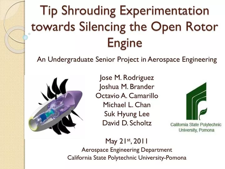
Tip Shrouding Experimentation towards Silencing the Open Rotor Engine. An Undergraduate Senior Project in Aerospace Engineering Jose M. Rodriguez Joshua M. Brander Octavio A. Camarillo Michael L. Chan Suk Hyung Lee David D. Scholtz May 21 st , 2011 Aerospace Engineering Department

E N D
Tip Shrouding Experimentationtowards Silencing the Open Rotor Engine An Undergraduate Senior Project in Aerospace Engineering Jose M. Rodriguez Joshua M. Brander Octavio A. Camarillo Michael L. Chan SukHyung Lee David D. Scholtz May 21st, 2011 Aerospace Engineering Department California State Polytechnic University-Pomona
Introductions Joshua Brander Lucerne Valley, CA Background & Interests: Automotive Racing Model Rocketry Project Contributions: Aerodynamics CAD/Design Computational Fluid Dynamics Jose M. Rodriguez et. al
Introductions Octavio Camarillo Anaheim, CA Background & Interests: Aerodynamics Structural Dynamics Project Contributions: Structural Analysis Jose M. Rodriguez et. al
Introductions Michael Chan Garden Grove, CA Background & Interests: CNC Programming/Machining Manufacturing & QA. Unmanned Aerial Vehicles Project Contributions: Aerodynamic Design Testing & Manufacturing Configuration/Integration Jose M. Rodriguez et. al
Introductions SukHyung Lee Seoul, Republic of Korea Background & Interests: Military Service- Infantry (Korea) PCB Design & Electronics Mfg Distinguished Honors Student Sigma Gamma Tau Tau Beta Pi Alpha Gamma Sigma Golden Key Int’l Project Contributions: Rapid Prototype Manufacturing Finite Element Methods/Structural Analysis Jose M. Rodriguez et. al
Introductions David Scholtz Ontario, CA Background & Interests: Logistics/Cargo Planning Math & Physics Tutoring Project Contributions: CAD/Design Graphics & Modeling Acoustic Measurement Jose M. Rodriguez et. al
Introductions Jose M. Rodriguez Apple Valley, CA Background & Interests: Military Service– U.S. Navy Aircraft Maintenance Flight Test/Operations Air Breathing Engines Turbomachinery Project Contributions: Project Manager Integration & Testing Acoustic Measurement Jose M. Rodriguez et. al
History & Background • Engines Commonly known as : • Open Rotor • “Propfans” • Unducted Fan Engines • External set of Counter-Rotating blades • Power Turbine-driven • Mechanically (gearbox) driven Courtesy of NASA GRC Jose M. Rodriguez et. al
History & Background Two Main Programs: • GE/NASA • UDF GE-36 • 1970’s-1989 • Turbine Driven • Pratt & Whitney-Allison • UHB 578-DX • 1986-1990 • Gearbox Driven Jose M. Rodriguez et. al
History & Background • Interest sparked in 1970’s due to rising fuel prices/Oil Embargos • Promising designs showed a 30% improvement in Fuel Efficiency Jose M. Rodriguez et. al
History & Background • Problems & Disadvantages: • Limited Mounting Configurations • High Vibrations imparted onto fuselage • Reduced Cruising Speeds • VERY LOUD!!!!! • In-cabin noise said to be extreme despite aft mounting on MD-80 series testbed aircraft • A reduction of approx. 30dB was needed to realize this concept Jose M. Rodriguez et. al
Why Study? • Interest in Open Rotor Engines is making a comeback due to increasing fuel/oil prices and “Green” revolution • GE/NASA Leap-X/CF34 • Rolls-Royce RB2011 • Pertinent & Interesting topic for senior project • Multi-faceted study Jose M. Rodriguez et. al
Our Approach • Attempt to silence by: • Understanding & Manipulating • Blade Tip Vortices • Blade Vortex Interaction (BVI) Noise • Turbulence Ingestion & Broadband Noise • Use of a shroud to reduce BVI & Broadband Noise • Minimize drag • Maximize blade exposure to free stream • Reduce Turbulent Wakefield Jose M. Rodriguez et. al
Our Approach • Mimic known good/previous work GE/NASA (Allison) Rolls-Royce Jose M. Rodriguez et. al
Tip Shrouding • Typical Fan shrouds encapsulate entire rotor • Drag becomes very unfavorable at high speeds • Tip Shroud: • Leaves over 70% of blade open to free-stream • Geometry creates much less drag than a conventional shroud Jose M. Rodriguez et. al
Tip Shrouding Jose M. Rodriguez et. al
Limitations • Manufacturing/Materials/Cost • Avoid Aerodynamic/Blade re-designs (Time) • Simple Mechanisms • Variable Pitch & control too complex • Basic power/drive method • Static Testing (ground conditions only) • Computing Power Jose M. Rodriguez et. al
Model Design • Desired to use GE UDF blade configuration with a variant of NASA SR-7 Blade • 12 Blade Front, 10 Blade Rear • Could not acquire appropriate airfoil data, etc. • Found P&W patent (expired 1996): • Provided airfoil coordinates and data for aerodynamically-correct modeling. Jose M. Rodriguez et. al
Design & CAD David D. Scholtz Jose M. Rodriguez et. al
Blade Modeling • Based off of UTC Patent # 4,730,985 • Provided: • cross-sectional data • coordinates & blade angles • Excel was used to convert 2D coordinates into 3D and rotate cross-section by associated blade angle • Used Solidworks® to model Jose M. Rodriguez et. al
Considerations in Blade Design • (Fixed-Pitch) Blade angle changed to run in static conditions • Decreased blade loading was desired • Blade Angle (BA): Angle from Chord Line to Plane of Rotation • BA was decreased from 75.86o by 41.86o to decrease b along blade • Root BA = 34.00o; Tip BA = 12.18o Jose M. Rodriguez et. al
Blade Angle Configuration Jose M. Rodriguez et. al
Build Considerations of Blades • Increased thickness of to allow scaling and manufacturability • Each half of airfoil face increased by .34 in, full scale to provide a scaled down thickness of .05 in. at the tip for model strength. Jose M. Rodriguez et. al
Rotor Modeling • Rotors were created on SolidWorks, via Circular Patterning feature. • Front (CW): • 10 blades • 6.50 in. diameter • Rear (CCW): • 8 blades • 5.71 in. diameter Jose M. Rodriguez et. al
Nacelles for Test Rig • Front and rear nacelles designed to allow smooth flow across rotors. Jose M. Rodriguez et. al
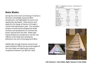
Tip Shrouds • Two models designed to experiment with • Model 1: • Basic circular shape, internally flat • Suspected would not be beneficial due to flow separation along inner wall of an un-cambered surface Jose M. Rodriguez et. al
Tip Shrouds • Model II: • Created with airfoil cross-section to augment flow across tip-shroud interface Jose M. Rodriguez et. al
Computational Fluid Dynamics Joshua M. Brander Jose M. Rodriguez et. al
CFD of Counter-Rotating Rotors • CD-Adapco STAR-CCM+ • Desired to Model Front CW and Aft CCW Rotor Blades simultaneously • Counter-Rotating Assemblies have very complex flows • Limited Computing Power Available • Modeled Front Assembly only Jose M. Rodriguez et. al
Turbulence Modeling • Flow Visualization • Trimmer Mesh Model w/ Prism Layer Mesher • 0.02 sec Time Step with 30 Inner Iterations/Step • K-Omega Turbulence Model • Pressure Distribution • Polyhedral Mesh Model with Prism Layer Mesher • Smaller Time Step Required Fine Mesh • 5 x 10⁻⁶ Time Step w/ 20 Inner Iterations per Step • K-Omega Turbulence Model Jose M. Rodriguez et. al
Front Rotor Flow Velocity M = 0.2 (ground operation/take-off conditions) 1000 RPM Clockwise (CW) Rotation Jose M. Rodriguez et. al
Pressure Distribution (Incoming Flow) Jose M. Rodriguez et. al
Pressure Distribution(Thrust Side) Jose M. Rodriguez et. al
Streamline Pattern @ 0.5 sec or 8 Rotations Jose M. Rodriguez et. al
Tip Vortex Visualization Jose M. Rodriguez et. al
Front Rotor w/ Flat Shroud Flow Velocity M = 0.7 1000 RPM Streamline @ 0.5 sec or 8 Rotations Jose M. Rodriguez et. al
Flow Velocity M = 0.2 1000 RPM Streamline @ 0.5 sec or 8 Rotations Visualization of Secondary Flows & Separation Jose M. Rodriguez et. al
Unfavorable Flow Separation @ Tips Jose M. Rodriguez et. al
Front Rotor w/ Augmented Shroud Flow Velocity M = 0.2 (ground operation/take-off conditions) 1000 RPM Clockwise (CW) Rotation Jose M. Rodriguez et. al
Pressure Distribution(Incoming Flow) Jose M. Rodriguez et. al
Pressure Distribution (Thrust Side) Jose M. Rodriguez et. al
Streamline Pattern @ 0.5 sec or 8 Rotations Jose M. Rodriguez et. al
Flow Remains Attached @ Tip-Shroud Interface Jose M. Rodriguez et. al
Structural Analysis Octavio A. Camarillo Jose M. Rodriguez et. al
Front Rotor Blade Loading • Pressure distribution modeled from CFD results of full scale model • Load magnitudes are percentages of full scale loading • Divided into four areas of different load intensity Jose M. Rodriguez et.al
Material Strength Jose M. Rodriguez et.al
Front Rotor Blade • Pre & Post processing using FEMAP • Analysis using NEiNASTRAN • Static Analysis • Blade will fail at 73% of CFD load • Max load of 9.5 psi Jose M. Rodriguez et.al
Rear Rotor Blade • No CFD simulation Available • Used pressure magnitude of the front blade’s downwash • Assumed Distribution to be same as the front blade’s. • Blade will fail at 36% of CFD load • Max Press. of 7.5 psi Jose M. Rodriguez et.al
Shroud • Shroud deformation analysis • Interest is in shroud critical deformation • Clearance must be kept between blade tips and shroud at all times • Critical Load at 30 psi • Deflection of 0.144 in Jose M. Rodriguez et.al
Rapid Prototype/Building SukHyung Lee Jose M. Rodriguez et. al