Download
1 / 16
190 likes | 403 Views
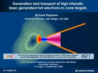
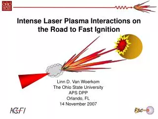
??. Laser. High Intensity Laser coupling to a cone geometry for fast Ignition. R.B. Stephens General Atomics. 10 th International Workshop on Fast Ignition of Fusion Targets Hersonissos, Crete, Greece 12-18 June 2008.

E N D
?? Laser High Intensity Laser coupling to a cone geometry for fast Ignition R.B. Stephens General Atomics 10th International Workshop on Fast Ignition of Fusion Targets Hersonissos, Crete, Greece 12-18 June 2008 This work was performed under the auspices of the U.S. Department of Energy under contracts No.DE-FG02-05ER54834 and Contract DE-AC52-07NA27344. IFT\P2008-068
Collaborators K.U. Akli L.V. Van Woerkom, R.R. Freeman, E. Chowdhury, D.W. Schumacher, D.T. Offermann, A. Link, V.M. Ovchinnikov F.N. Beg,T. Ma, S. Chawla, T. Bartal, M.S. Wei, J. King,J. Pasley A.J. MacKinnon, A.G. Macphee, M. H. Key, H. Chen, R. Town, M. Foord, S. P. Hatchett, A.J. Kemp, A. B. Langdon, B. F. Lasinski, P. K. Patel, M. Tabak, T.H.Phillips D. Hey C. Chen, M. Porkolab Y. Tsui H. Habara, R. Kodama, H. Nakamura, K. Tanaka, T. Tanimoto R. C. Clarke, J. Green, K. Lancaster, P. Norreys, D. Neely
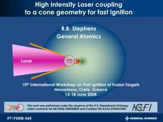
A reentrant cone defines the Laser Plasma Interface • Ignition parameters • Laser: I ~ 1020 W/cm2, ~ 10-20 psec, E ~ 100 kJ • Cone: tip, fuel size ~ 40 m • Must generate electrons that will stop at the core • Range < 1.5 g/cm2 • Forward directed • How does the cone affect electron parameters? • Energy spectrum • Conversion efficiency • Directionality Atzeni et al., POP 05702 (2007)
Cu K imager Spectralon • Tested with flat foils • Tested with thin-walled Cu cones Cu K imager Cone could have several effects Good • Shape to focus light to tip • Walls to guide electrons to tip Bad • Confinement enhance effects of preplasma 75°
S pol - 10 mAl/25mCu/1mmAl P pol - 10 mAl/25mCu/1mmAl 60 S pol - 25mCu 50 40 30 0 40 80 120 160 200 240 20 10 0 Reflectivity moderate at glancing incidence Specular Reflectivity, % = 75° • Reflectivity apparently decreases with increasing power • Difference between S- & P- polarizations within errors = 28° Laser Peak Power, TW
3000 super-Gaussian fit tp reflected beam 2500 2000 Signal, arb. units 1500 1000 f/3 input beam 500 0 0 50 100 150 200 250 Distance, mm Incident Reflected Incident Reflected Reflected light is partially scattered • Input beam is f/3, reflected beam f/2 • Mask shadow disappears in reflected beam • Light focusing with cone wall has limited benefit
Eprepulse~20 mJ Eprepulse~400 mJ 20070830 s04 ka1 20070830 s03 ka1 20070827 s01 ka2 Near Normal Incidence Glancing Incidence e- Generation at glancing incidence is weak and localized • K production substantially reduced so e- generation is very weak • Fluorescence shows no electrons forward from beam • Not changed by pre-plasma • e- generation on cone wall not useful Color scale shifted 7x
4.0 3.5 3.0 2.5 2.0 1.5 Relative Inner shell ionization cross-section 1.0 0.5 3 2 1 4 10 10 10 10 Kinetic Energy (keV) Any significant electron flow would be visible H. Habara et al., Phys. Rev. Lett 97, 095004 (2006) • A few electrons been observed leaving target • Forward directed surface electrons detected with electron spectrometer. • Depends on target size - preplasma expansion can increase numbers. • Most electrons are trapped on the target • Losing 2x10¹¹ electrons charges 1/2 mm sphere to MV • If all MeV electrons, loss of 30 mJ ( < 0.1% absorbed energy) • Current flowing up support stalk insignificant ~106 electrons • All trapped electrons can be seen • Target only 25 m thick (~ K abs length) • Scattering cross section ~ independent of energy • No significant e flows along the surface T.Yabuuchi et al., Plasm & Fus Res 1,1 (2006)
Eprepulse~20 mJ Eprepulse~400 mJ 20070830 s04 ka1 20070830 s03 ka1 20070827 s01 ka2 Near Normal Incidence Glancing Incidence e- Generation at glancing incidence is weak and localized • K production substantially reduced so e- generation is very weak • No significant electrons forward from beam • Not changed by pre-plasma • e- generation on cone wall not useful Color scale shifted 7x => And best strategy is to focus light on cone tip
20070823s03 700 m But electrons spread a few hundred m up the cone Tight focus at tip Imaged K fluorescence of Cu cones shows electrons spreading unlike foils Laser focus is smaller than flat cone tip -- should expect electrons concentrated at the tip L. Van Woerkom et al., Phys. of Plasmas 15, 056304 (2008).
Cones 3X Slabs 28° incidence 1011 Slabs 75° incidence Yield (Ph/J/sr) 1010 109 1017 1018 1019 1020 1021 Peak intensity (W/cm2) 3X higher K emission from cones compared to foils Where are they generated and which are useful?
e- distribution in the cone not sensitive to focus 20070504s06 20070504s05 20070504s04 900 mm behind 450 mm inside 450 mm behind
Cu K1 Electron locations independent of focus • Probably caused by plasma filling during prepulse • ~10-20 mJ during ~2 ns • Cones act like a ~300 m deep bucket for energy coupling • Electrons are free to travel within that space • Adding more prepulse energy deepens the bucket • 1 Joule of prepulse nearly fills it.
1 mm Cu K - 8 keV XUV - 256 eV Electrons do couple to the tip • Previous shots at Vulcan showed similar plasma filling effects • Indication of heating (XUV) partway up the cone independent of focus location • And still strong coupling to electrons in wire • 15% for 40 m dia wire
Plans for integrated e- generation tests this Summer • Previous experiments did not have sufficient information • Prepulse and focus now measured on each shot at Titan • Prepulse reduced to ~ 3 mJ • Cone wire - e coupling into wire • Sensitivity of coupling to prepulse energy • Buried cones - electron generation • Thick walls simulate blow-off plasma • Image buried layer fluorescence to see electrons directions • Bookend - (2D cones) • Study confined plasma
Maximize efficiency by good focus and limited prepulse • Modest reflection at glancing incidence, minimal electron generation • Low reflection at normal incidence, maximum electron generation • No significant electron flow along surface • Maximize light intensity at tip with no reflection • Reflections just to add wings of focus in • Compound Parabolic Collector has the right properties • Single bounce gets all light to the tip • Concentrates light proportional to f/number • Possible improvement limited • Reflectivity ~ 50% - only use reflections to gather in wings of focal spot • Effective cone length limited by forward scattering - < 100 m • Near-critical plasma fill can refocus/filament light • Must limit prepulse? • 20 mJ filled cone 300 m deep • But current still coupled to wire • What’s the tolerable limit??