Download
1 / 60
600 likes | 734 Views
This research presents the development of Plasma Panel Particle Detectors (PPPD) that leverage the principles of plasma display panels to enhance detection and imaging capabilities. By eliminating the need for gas flow and using hermetically sealed designs, these streamlined sensors promise cost-effective manufacturing and scalability. Key enhancements include high timing resolution (approx. 1 ns), granularity (50-200 µm), and potential applications in nuclear physics, medical imaging, and homeland security. This innovation offers promising advancements in particle detection technologies and sensor applications.

E N D
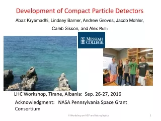
Development of Plasma Panel Particle Detectors Yiftah Silver Tel-Aviv University Dec. 18 2013
Collaborators • Tel Aviv University, School of Physics & Astronomy Yan Benhammou, Meny Ben Moshe, Erez Etzion, Yiftah Silver • Integrated Sensors, LLC Peter Friedman • University of Michigan, Department of Physics Robert Ball, J. W. Chapman, Claudio Ferretti, Daniel Levin, Curtis Weaverdyck, Riley Wetzel, Bing Zhou • Oak Ridge National Laboratory, Physics Division Robert Varner, James Beene • Ion Beam Applications S.A. (IBA, Belgium) Hassan Bentefour • General Electric Company, Reuter-Stokes Division (Twinsburg, OH) Kevin McKinny, Thomas Anderson Y. Silver Tel-Aviv University 2 2 2
Outline Motivation Plasma display panel (PDP) operational principles Plasma panel sensor (PPS) description Simulations Lab results Next generation design Summary Y. Silver Tel-Aviv University 3 3 3
Motivations • Hermetically sealed • no gas flow • no expensive and cumbersome gas system • Over 40 years of plasma panel manufacturing & cost reductions ($0.03/cm2 for plasma panel TVs) • Potential for scalable dimensions, low mass profile, long life • meter size with thin substrate capability • Potential to achieve contemporary performance benchmarks • Timing resolution approx 1 ns • Granularity (cell pitch) 50-200 µm • Spatial resolution tens of µm • Potential applications in • Nuclear and high energy physics, medical imaging, homeland security, etc Y. Silver Tel-Aviv University 4 4
TV Plasma Panel Structure A Display panel is complicated structure with • MgO layer • dielectrics/rib • phosphors • protective layer Y. Silver Tel-Aviv University 5 5 5
TV Plasma Panel Structure • For detector, a simplified version with readout & quench resistor • No MgO layer • No dielectric/rib • No phosphors • No protective layer Y. Silver Tel-Aviv University 6 6 6
Commercial Panel Designs Columnar Discharge (CD) Surface Discharge (SD) Two basic configurations for the electrodes: CD and SD Discharge dimensions ≈ 100 µm Gas pressure ≈ 400-600 Torr (usually Ne, Xe, Ar, Kr, He) Applied voltage typically hundreds of volts Y. Silver Tel-Aviv University 7 7
Commercial Panel Designs • Two operational modes: • AC televisions, monitors employ dielectric layers on electrodes • DC dot-matrix displays use directly facing metalized anodes & cathodes Y. Silver Tel-Aviv University 8 8
Commercial Plasma Panel • Columnar Discharge (CD) – Pixels at intersections of orthogonal electrode array • Electrodes sizes and pitch vary between different panels 220 –450 µm Y. Silver Tel-Aviv University 9 9
PPS with CD-Electrode Structure(≈ 20-25% active cell/pixel fill-factor) Y. Silver Tel-Aviv University 10 10 10
PDP PPS • Remove or procure without gas • Alter manufacturer’s electrode material (replace SnO2 with Ni ) • Add a custom gas port and high quality VCR valve • Subject panel to extended pump down, bake-out • Fill with commercial or in-house gas mixture • Close valve, mount panel for exposure to source or CR trigger • Configure with HV feed, quench resistors, signal readout & DAQ • Panels operable for several months (even 1 year) after gas-filling without hermetic seal (i.e. only with “closed” shut-off valve) • Investigate the behavior for different conditions • Gas composition, pressure, HV, termination, Electrode materials • Sources and Configurations • , CR & test beam muons, beam protons, neutrons, gammas • Triggered, untriggered, collimated, uncollimated Y. Silver Tel-Aviv University 11 11
Modified Commercial Panel (fill-factor 23.5%, cell pitch 2.5 mm) “Refillable” gas shut-off valve for R&D testing Y. Silver Tel-Aviv University 12 12 12
cathode Principles of Operation 10-1000 M HV(-) Charged particle track • Accelerated electrons begin avalanche • Large electric field leads to streamers • Streamers lead to breakdown- roughly follows Paschen’s law. “A Theory of Spark Discharge”, J. M. Meek, Phys. Rev. 57, 1940 50 µm -1mm anode 250 µm -1mm Gas volume in pixel • Gas gap becomes conductive • Voltage drops on quench resistor • E-field inside the pixel drops • Discharge terminates 50-100 Y. Silver Tel-Aviv University 13 13 13 13
Paschen discharge potential Lieberman and Lichtenberg, Principles of Plasma Discharges, Wiley 2005. • x = pressure * gap x0 = 1 Torr cm • a, b = gas specific parameters V A.K. Bhattacharya, GE Cor Phys. Rev. A, 13,3 (1975) Small variations in Penning mixtures dramatically affect breakdown voltage Y. Silver Tel-Aviv University
Electromagnetic Field Model • Each cell is modeled as a capacitor • COMSOL model for the electric field inside the cell • Capacitances and inductances are also calculated E-field in the PDP pixels No E-field 5 mm 0 -5 mm E-field is localized Y. Silver Tel-Aviv University 15 15 15 15
Equivalent Circuit Simulations • SPICE simulation incorporates the inductances and capacitances calculated with COMSOL • Electrical pulse is injected into the cell and the output signal is simulated Single cell SPICE model Many cells SPICE model Y. Silver Tel-Aviv University 16 16 16 16
SPICE Simulated Signal free parameters total charge, width of “” function Y. Silver Tel-Aviv University
Design & Operating Parameters • Cell Design: fill-factor • - open vs. closed architecture • - columnar vs. surface discharge • Electrodes: pitch, width, material • Cell capacitance • Operating voltage • Quench resistance • Gas mixture & pressure • Substrate material (e.g. thickness, density) • Dielectric surfaces Y. Silver Tel-Aviv University 18 18
Performance Issues( some of which we have begun to address ) • After pulsing & discharge spreading • Gas hermeticity & decomposition • Response in magnetic field • Electrode degradation • Radiation hardness • High rate response • Spatial uniformity • Spatial response • Time response • Efficiency • Readout • Cost Y. Silver Tel-Aviv University 19 19
Experimental Results All results reported here obtained with prototype detectors adapted from: glass sealed, open architecture, columnar discharge, monochromatic, DC display panels shut-off valve “seal” Y. Silver Tel-Aviv University 20 20
Signals from Panel • pulse from Xe fill 2003, tested 2010 1 mm electrode pitch panel sealed & tested in 2013, pulse from neutron source & 3He fill Signals amplitudes: volts Good signal to noise ratios. Fast rise times O(ns) Pulse shape uniform for a given panel design 2.5 mm electrode pitch 30 V Y. Silver Tel-Aviv University 21 21 21 21
Response to Source vs applied High Voltage Y. Silver Tel-Aviv University 22
Quench Resistance Dependence ( Characteristic Response Curve ) Saturation Working Region Secondary Pulses Y. Silver Tel-Aviv University 23 23 23
Position SensitivityProton Test beam & Lab Y. Silver Tel-Aviv University 24 24 24
PPS Proton Test Beam March 2012 IBA ProCure Facility - Chicago Y. Silver Tel-Aviv University 25 25 25
IBA Proton Beam Test • Beam energy 226 MeV, Gaussian distributed with 0.5 cm width • Proton rate was larger than 1 GHz on the entire spread of the beam Y. Silver Tel-Aviv University 26 26 26 26
Position Scan • Two position scans (panel filled with 1% CO2 in Ar at 600 Torr) • 1 cm steps - using brass collimator with 1 cm hole, 2.5 cm from beam center • 1 mm steps with 1mm hole directly in beam center • Rate of protons through 1mm hole in center of beam was measured at 2 MHz The Panel Y. Silver Tel-Aviv University 27 27 27 27
1mm Scan Reconstructed centroid of hit map vs. PDP relative displacement with respect to the panel’s initial position Number of hits per channel Y. Silver Tel-Aviv University 28 28 28 28
Collimated Source Position Scan 106Ru collimated source • Light-tight , RF shielded box • 1 mm pitch panel • 20 readout lines • 1.25 mm wide graphite collimator Motorized X-Y table Test Panel Y. Silver Tel-Aviv University 29 29
Collimated β-Source Simulation Primary electrons exiting the graphite collimator Y. Silver Tel-Aviv University 30 30 30 30 30
Dispersion of β-Particles in Panel(simulation) Geant4 simulation: 106Ru ’s 1.25 mm slit collimator 2.25 mm glass Y. Silver Tel-Aviv University 31 31 31 31
Source Moved in 0.1 mm Increments (1 mm pitch panel) Y. Silver Tel-Aviv University 32 32 32
PPS Position Scan Mean fit for β-source moved in 0.1mm increments * *Electrode Pitch 1.0 mm Centroid measurement consistent with electrode pitch Y. Silver Tel-Aviv University 33 33 33
Position Resolution/Dispersion source Electrode Pitch =1.0 mm 2res = 2meas- 2MC Position resolution < 1 mm Y. Silver Tel-Aviv University 34 34 34
PPS Cosmic-Ray Muon Results Y. Silver Tel-Aviv University 35 35
Cosmic Muon Measurement Setup Trigger is 3”x 4’’ scintillation pads 24 RO channels 30 HV lines Y. Silver Tel-Aviv University 36 36 36 36
CR Muon Response 2.5 days Y. Silver Tel-Aviv University 37 37
Response over active region All channels active exhibit similar levels of activity Y. Silver Tel-Aviv University 38 38
Time Spectrum = 40.1 0.9 Ar / 1% CF4 at 730 Torr 1100V Pulse “arrival” time (includes arbitrary trigger offset) = timing resolution (jitter) of the detector We repeat this measurement with various gases and voltages Y. Silver Tel-Aviv University 39 39
Time Spectrum Ar / 1% CF4 at 730 Torr Y. Silver Tel-Aviv University
Timing Resolution vs. Applied HV Mean arrival time Sigma of arrival time Ar / 1% CF4, 600 Torr Ar / 1% CF4, 600 Torr Ar / 1% CF4, 730 Torr Ar / 1% CF4, 730 Torr Ar / 10% CF4, 730 Torr Ar / 10% CF4, 730 Torr Y. Silver Tel-Aviv University 41 41 41 41
Timing Resolution using 65% He 35 % CF4 at 730 Torr ~ 10 ns HV =1290 V • trigger time subtracted; • arbitrary cable offset Y. Silver Tel-Aviv University
Timing Resolution using 80% 3He 20 % CF4 at 730 Torr ~ 3.5 ns HV =1030 V trigger artifacts • trigger time subtracted; • arbitrary cable offset Y. Silver Tel-Aviv University
PPS Area Corrected Efficiency (10% CF4 in Ar, at 740 Torr, 0.38 mm gas gap) Maximum Pixel Efficiency: 60% pixel efficiency = 53% ( 88% of maximum possible) • Assumptions: • Uniform trigger response • Constant effective pixel size Y. Silver Tel-Aviv University 44 44 44
PPS Muon Test Beam November 2012 H8 at CERN
Setup 8 HV lines 100 MΩ quenched Ni-SnO2 PPS Ar / 7% CO2 600 Torr HV = 1090 V OR 16 channels 180 GeV BEAM AND AND 2 scintillation pads 4 cm2 each Panel active area is 2cm x 4cm Y. Silver Tel-Aviv University 46 46
Time Resolution • Timing resolution with • Ar-CO2better than 10nsec • Geometrical acceptance times efficiency ≈ 2% (pixel efficiency is much higher). Did not have beam time to optimize or even raise the voltage! • Active area fill-factor for PPS detector is 23.5% Y. Silver Tel-Aviv University 47 47 47 47 47
Neutron Detectionin collaboration with GE, Reuter-Stokes Objectives: high efficiency neutron detectors with high rejection develop alternate to 3He as neutron interaction medium This test: explore PPS as a general detector structure for converting neutrons using thin gap 3He gas mixture Gas fill: 80% 3He + 20% CF4 at 730 Torr Panel: 2.5 mm pitch large panel used for CR muons Instrumented pixels = 600 Area: 6 in2 Method:irradiate panel with thermal neutrons from various sources high activity (10 mrem/hr) gammas conduct count rates experiment with & w/o neutron mask plates. Y. Silver Tel-Aviv University
Setup Gamma transparent, neutron blocking plates (~ 0.1% transmission ) PPS panel neutron sources 252 Cf , 241Am-Be, 239Pu-Be nested in stainless capsule, Pb cylinder, high density polyethylene (HDPE) Y. Silver Tel-Aviv University
PPS panel Results neutron source ( 252 Cf ) Neutron blocking plate efficiency plateau Background subtracted data is neutrons only Background: from source Y. Silver Tel-Aviv University