Download
1 / 22
220 likes | 373 Views
Punch through protection and p-stop ion concentration in HPK strip mini-sensors. Jan Bohm , Institute of Physics ASCR, Prague Peter Kodys , Pavel Novotny, Tomas Jindra , Zdenek Dolezal , Jan Scheirich , Charles University in Prague

E N D
Punch through protection and p-stop ion concentration in HPK strip mini-sensors Jan Bohm, Institute of Physics ASCR, Prague Peter Kodys, Pavel Novotny, Tomas Jindra, ZdenekDolezal, Jan Scheirich, Charles University in Prague PetrMasek,Michael Solar,Institute of Experimentaland Applied Physicsof Czech Technical University in Prague J.Bohm, 20th RD50 Workshop, Bari, Italy
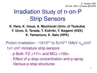
Survey The performance of the sample of 75 n-in-p HPK miniature 1cm*1cm sensors developed by ATLAS Collaboration for LHC upgrade [Y. Unno, et.al., Nucl. Inst. Meth. A636 (2011) S24-30] with different punch through structures, BZ4A-D, and with three different ion concentrations of 2E12, 4E12 and 1E13 ion/cm^2 of the P-stop and P-stop + P-spray separation is studied before and after irradiation. This report is a compilation of measured characteristics before irradiation.The second part of this study, i.e. after irradiation, will be available soon. -Description of the sample of miniature sensors -Bulk characteristics, IV and CV measurement -Punch Through Protection and PT voltages -Interstrip capacitance -Interstrip resistance ------------------------------------------------------- -Thermal dependence of poly-silicon bias resistors of non-irradiated and of irradiated sensors up to 4E14neq/cm^2. J.Bohm, 20th RD50 Workshop, Bari, Italy
Sample of miniature sensors From Hamburg we received next 12 sensors BZ4A-D of Series 3 (wafers 264,278 and 281) with P-stop ion concentration 4E12 ion/cm^2. Many thanks to colleagues from DESY. The micro-strip silicon miniature sensors of 1cmx1cm (strip length 0.8cm) are ATLAS07 Series fabricated by Hamamatsu Photonics (HPK) using 6” (150 mm) process technology . The baseline is p-type float zone silicon with crystal orientation <100> and having thickness of 320 μ. Sensors are single-sided with AC coupled readout n-typestrips which are biased through polysilicon resistors. One hundred readout strips with pitch 74.5 μ are electrically isolated by a common and floating p-implant (‘p-stop’ isolation) J.Bohm, 20th RD50 Workshop, Bari, Italy
IV characteristics Measured sensors were placed on the table without vacuum chuck jig to avoid possible strong stresses which could cause breakdowns. J.Bohm, 20th RD50 Workshop, Bari, Italy
IV characteristics All sensors with p-stop isolation and with different ion concentrations were successfully operating up to 1000V, no onset of micro-discharges was observed. On other side, sensors with P-stop + P-spray isolation behaves differently and an onset of breakdowns are above already Vbias=900V. J.Bohm, 20th RD50 Workshop, Bari, Italy
CV Characteristics Bulk capacitance has been measured on sensors BZ4D at each wafers. Sensors BZ4A-D from wafer W75 of Series 2 STD have higher full depletion voltage, Vfd=286V J.Bohm, 20th RD50 Workshop, Bari, Italy
CV Characteristics Bulk capacitance does not depend on testing frequency in range of 200Hz up to 20kHz *) Sensors BZ4A-D from wafer W75 of Series 2 STD have higher full depletion voltage, Vfd=286V J.Bohm, 20th RD50 Workshop, Bari, Italy
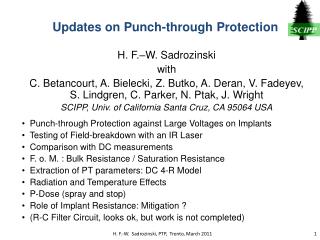
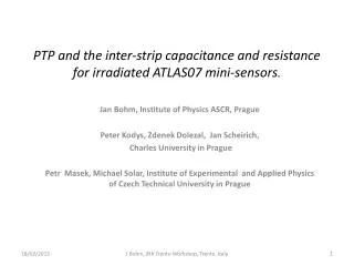
Punch Through Protection Structures A protection of AC coupling capacitors against the beam splashes should ensure special structures, Z4A,B,C and D on the HPK ATLAS07 mini-sensors. A beam splash generates a spike of voltage across the AC coupling insulator. When the distance between the bias rail and the n-strip implants is appropriate, this voltage between the bias rail and the n-strip implant ends can be limited. This distance is 20 µ and is used in sensor Z4D without any other structure. J.Bohm, 20th RD50 Workshop, Bari, Italy
Punch Through Protection Structures Bias Ring DC pad NEAR END Vtest DC pad FAR END PT structure Rpt n+ implant R implant Rbias Itest DC method S.Lindgren et.al NIM A636(2011)S111-S11& Reff=dVtest/dItest, where Vtest is an applied voltage (Uappl) to DC pad and Itest is an current between DC pad and the bias ring. Rpt is supposed to be parallel to Rbias: 1/Reff=1/Rbias+1/Rpt. Punch-Through Voltage is the Test Voltage for Rbias=Rpt, i.e. forReff=Rbias/2. PT voltage is evaluated at bias voltages 100, 300, 500, 700 and 900V for PT structures Z4A-D J.Bohm, 20th RD50 Workshop, Bari, Italy
Punch Through Protection Structures - Rpt Vbias=-300V Calculated Rpt‘s as a function of Itest for the same structure, BZ4C, and different bias voltages are the same contrary to Rpt’s evaluated for different PT structures but the same bias voltage which show different dependences. Structure BZ4A is very effective at high current. J.Bohm, 20th RD50 Workshop, Bari, Italy
Punch Through Protection Structures - Rpt Structure BZ4A it seems to be the most effective short at low currents : -7µA, -18µA and -26µA for P-stop ion concentration 2E12, 4E12 and 1E13 ion/cm^2 , respectively. J.Bohm, 20th RD50 Workshop, Bari, Italy
Punch Through Voltage 1e13 ion/cm^2 P-stop+P-spray 2E12 ion/cm^2 4E12 ion/cm^2 2E12 ion/cm^2 FAR END -Punch through voltage dominantly depends on P-stop ion concentration for all punch through structures. -PT voltage for P-stop+P-spray isolation is considerable higher than for P-stop isolation at same p-dose 2E12 ion/cm^2 -Differences among PT voltages for each structure BZ4A-D are small for all concentrations, several volts only -PT voltage increases with applied bias, for concentration 1E13 ion/cm^2 is observed nearly saturation for Vb>500V. -PT voltages are smaller than 50V, i.e. they are significantly below the hold-off voltage of the coupling capacitor which are typically tested to 100V. Punch through protection structures will be tested soon by laser technique. J.Bohm, 20th RD50 Workshop, Bari, Italy
Punch Through Protection Structures J.Bohm, 20th RD50 Workshop, Bari, Italy
Interstrip Capacitance - Method of measurement 5-probes 3-probes 2-probes DC pad AC pad LCR High LCR Low Cint(5-pr)/Cint(3-pr)=0.939 and 0.913 for 100kHz and 1MHz, respect. Cint(2-pr)/Cint(5-pr)=0.57 Isolated strips to GND J.Bohm, M.Mikestikova et.al, NIM A636 (2011)S104-S110 J.Bohm, 20th RD50 Workshop, Bari, Italy
Interstrip Capacitance Interstrip capacitance is measured by 3 probes. C interstrip depends strongly on frequency. Capacitance is measured at 1MHz For Vbias<Vfd the values of C interstrip depend on the P-stop & P-spray ion concentration . There is narrow deep minimum of Cint at Vbias =-4V for P-stop+P-spray isolation. J.Bohm, 20th RD50 Workshop, Bari, Italy
Interstrip Capacitance Interstrip capacitance in this table was evaluated for Vbias=Vfd+10V The inter-strip capacitance, Cint, is constant for bias voltages higher than respective full depletion voltages and Cint does not depend in this region on an ion concentration and the punch through protection structures within ±20fF. Possible time dependence of Cint and an influence of relative humidity is in progress. J.Bohm, 20th RD50 Workshop, Bari, Italy
Interstrip Resistance I AC pad V V DC pad Rbias PT structures Bias ring Rint = 2*dV/dI measured at Vbias=-50V, -100V and -300V Interstrip resistance increases with P-stop ion concentration from 4E12ion/cm^2 up to 1E13 ion/cm^2 J.Bohm, 20th RD50 Workshop, Bari, Italy
Interstrip Resistance Interstrip resistance for case of P-stop + P-spray isolation is about two times higher than one for P-stop isolation for all punch through structures with exception of BZ4B. The interstrip resistance dependence on ion concentration can be estimated for Z4D structure : Rint=4E-11xIons/cm^2+103.8G Presumably not only ion concentration is responsible for Rint value but also fabrication processes in various series. J.Bohm, 20th RD50 Workshop, Bari, Italy
Thermal Dependence of Polysilicon Bias Resistor PT voltage is slightly higher for low temperature (-30C) than for room temperature (24C). The difference is explained by lower bias resistance for room temperature than for -30C. Points in the figure are taken at -80V. Temperature was measured at each bias voltage. Both methods used for the evaluation of Rbias dependence on temperature gave the same slope of -0.0067 MΩ/1°C J.Bohm, 20th RD50 Workshop, Bari, Italy
Thermal Dependence of Poly silicon Bias Resistor An evidence that the thermal coefficient of poly-silicon bias resistor increases with fluency? The respective temperature coefficients are -6.7kΩ/1°Cfor non-irradiated sensors and -10.1kΩ/1°Cfor fluency 4e14neq/cm^2 J.Bohm, 20th RD50 Workshop, Bari, Italy
Summary All sensors ATLAS07 with p-stop isolation and with different ion concentrations were successfully operating up to 1000V, no onset of micro-discharges was observed. On other side, sensors with P-stop + P-spray isolation behave differently and an onset of breakdowns are above already Vbias=900V. Full depletion voltages of tested sensors are in the range of 180V-290V Punch through voltage dominantly depends on the P-stop ion concentration for all punch through structures. PT voltage for P-stop+P-spray isolation is considerable higher than one for P-stop isolation at same p-dose 2E12 ion/cm^2. PT voltage increases with applied bias. PT voltages are smaller than 50V, i.e. they are significantly below the hold-off voltage of the coupling capacitor which are typically tested to 100V. Study of Rpt dependence on the test current shows that the most effective short, i.e. protection against beam splashes , ensures the structure BZ4A for all tested P-stop ion concentrations. The inter-strip capacitance, Cint, is constant for bias voltages higher than respective full depletion voltages and Cint does not depend in this region on an ion concentration and the punch through protection structures within ±20fF. Interstrip resistance increases with P-stop ion concentration from 4E12 up to 1E13ion/cm^2 The polysilicon bias resistance depends on temperature. The respective temperature coefficients are -6.7kΩ/1°C for non-irradiated sensors and -10.1kΩ/1°C for fluency 4e14neq/cm^2 . J.Bohm, 20th RD50 Workshop, Bari, Italy