Download
1 / 9
90 likes | 260 Views
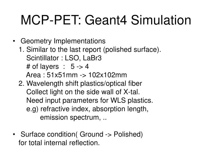
MCP-PET: Geant4 Simulation. Geometry Implementations 1. Similar to the last report (polished surface). Scintillator : LSO, LaBr3 # of layers : 5 -> 4 Area : 51x51mm -> 102x102mm 2. Wavelength shift plastics/optical fiber

E N D
MCP-PET: Geant4 Simulation • Geometry Implementations 1. Similar to the last report (polished surface). Scintillator : LSO, LaBr3 # of layers : 5 -> 4 Area : 51x51mm -> 102x102mm 2. Wavelength shift plastics/optical fiber Collect light on the side wall of X-tal. Need input parameters for WLS plastics. e.g) refractive index, absorption length, emission spectrum, .. • Surface condition( Ground -> Polished) for total internal reflection.
Layer 1 Layer 2 Layer 3 Layer 4 N. B.: NOT TO SCALE C R Y S T A L C R Y S T A L C R Y S T A L C R Y S T A L Sample Crystal MPC Wave Shifter Bar + Fiber Optic Legend Transmission Line Anode MCP 4a MCP 1a MCP 2a MCP 2b MCP 3a MCP 3b MCP 1b MCP 4b Photocathode MCP Channel plates Transmission Lines Wave-Form Sampling Electronics Wave Shifter + Fiber Optic 4-Layer Micro-Pet Sampling Calorimeter Wave-Form Sampling Electronics
Emission Spectra(input to geant4) LSO LaBr3 MCP Q.E(Burle Planacon) nm nm nm
Emission Spectra(geant4 output) nm nm LaBr3 LSO Emission spectra of LSO, LaBr3 Before/After MCP Q.E applied
# of photoelectron at photo-cathode # of p.e ( LSO) LaBr3 • # of p.e at 1st lalyer • Sum of 2 sides( front and back) • 371 for LSO • 976 for LaBr3( ~2.6 times larger than LSO) • LaBr3 has more compton scattering events.
Hit layer(1,2,3,4) 1 2 3 4 layer LaBr3 LSO Shows that LSO has higher stopping power than LaBr3.
Detection Efficiency ? LaBr3 # of photo-electron(LSO): sum of 4 layers • Requiring • # of photo-electron > 50. • Mutiple layers can • have hits in an events. • ( by compton scattering)
Light spread( at photo-cathode) mm mm X of p.e ( Single event) RMS of the X spread Light spread : RMS ~ 4.5mm Consistent with simple calculation: crystal length : 10mm rindex : 1.82(LSO) -> 1.00 critical anlge : 33.3 deg 10mm*tan(33.3) = 6.5mm X of p.e ( all the first layer hits)
Plans • Investigate material effects 4mm of T-Line width. • Extract Energy, Timing resolution • Implement WLS bar/ fiber