Download
1 / 17
170 likes | 266 Views
This presentation covers FCC rules, proper station setup, antenna fundamentals, and emergency communications in amateur radio technician classes. Discover various antenna types, gains, and their relationships with frequencies. Understand radio wave propagation, reflections, and signal fading for efficient communication. Be equipped with knowledge on the advantages and disadvantages of different antennas and signal behavior in different terrains.

E N D
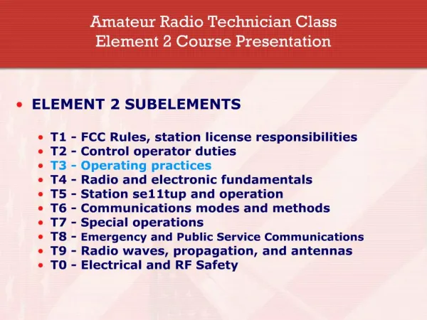
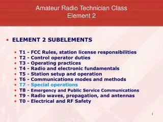
Amateur Radio Technician ClassElement 2Course Presentation • ELEMENT 2 SUBELEMENTS • T1 - FCC Rules, station license responsibilities • T2 - Control operator duties • T3 - Operating practices • T4 - Radio and electronic fundamentals • T5 - Station setup and operation • T6 - Communications modes and methods • T7 - Special operations • T8 - Emergency and Public Service Communications • T9 - Radio waves, propagation, and antennas • T0 - Electrical and RF Safety
SUBELEMENT T9 - Radio waves, propagation, and antennas[3 exam questions – 3 groups] T9A – [1 exam question] • Antenna types – vertical, horizontal • A vertical antenna is an antenna that consists of a single element mounted perpendicular to the Earth's surface. • A horizontal antenna is a simple dipole mounted so the elements are parallel to the Earth's surface.
SUBELEMENT T9 - Radio waves, propagation, and antennas[3 exam questions – 3 groups] T9A – [1 exam question] • Concept of gain • A beam antenna is an antenna that concentrates signals in one direction. • The quad, Yagi, and dish are all types of directional or beam antennas. • The advantage of 5/8 wavelength over 1/4 wavelength vertical antennas is their radiation pattern concentrates energy at lower angles.
SUBELEMENT T9 - Radio waves, propagation, and antennas[3 exam questions – 3 groups] T9A – [1 exam question] • Common portable and mobile antennas, losses with short antennas • A disadvantage of the "rubber duck" antenna supplied with most hand held radio transceivers is it does not transmit or receive as effectively as a full sized antenna. • A good reason not to use a "rubber duck" antenna inside your car is that signals can be 10 to 20 times weaker than when you are outside of the vehicle. • A magnet mount vertical antenna is one type of antenna that offers good efficiency when operating mobile and can be easily installed or removed.
SUBELEMENT T9 - Radio waves, propagation, and antennas[3 exam questions – 3 groups] T9A – [1 exam question] • Relationships between antenna length and frequency • The physical size of half-wave dipole antenna becomes shorter as the operating frequency increases. • The approximate length, in inches, of a quarter-wavelength vertical antenna for 146 MHz is 19 inches. [Remember the relationship between wavelength and frequency.] • The approximate length, in inches, of a 6-meter 1/2 wavelength wire dipole antenna is 112 inches. [Remember the relationship between wavelength and frequency.]
SUBELEMENT T9 - Radio waves, propagation, and antennas[3 exam questions – 3 groups] T9A – [1 exam question] • Dummy loads • The primary purpose of a dummy load is it does not radiate interfering signals when making tests. [Actually, it may radiate but the signal level radiated is usually well attenuated.]
SUBELEMENT T9 - Radio waves, propagation, and antennas[3 exam questions – 3 groups] T9B – [1 exam question] • Propagation • VHF/UHF signals not normally heard over long distances due to VHF and UHF signals usually not being reflected by the ionosphere. • When we hear a VHF signal from long distances a possible cause is sporadic E reflection from a layer in the ionosphere.
SUBELEMENT T9 - Radio waves, propagation, and antennas[3 exam questions – 3 groups] T9B – [1 exam question] • Fading, Multipath distortion • Picket fencing is a term commonly used to describe the rapid fluttering sound sometimes heard from mobile stations that are moving while transmitting. • If a station reports that your signals were strong just a moment ago, but now they are weak or distorted, try moving a few feet, random reflections may be causing multi-path distortion. • The most likely cause of sudden bursts of tones or fragments of different conversations that interfere with VHF or UHF signals is when strong signals are overloading the receiver and causing undesired signals to be heard.
SUBELEMENT T9 - Radio waves, propagation, and antennas[3 exam questions – 3 groups] T9B – [1 exam question] • Reflections • A way to reach a distant repeater if buildings or obstructions are blocking the direct line of sight path is to try using a directional antenna to find a path that reflects signals to the repeater.
SUBELEMENT T9 - Radio waves, propagation, and antennas[3 exam questions – 3 groups] T9B – [1 exam question] • Radio horizon, Terrain blocking • The radio horizon is the point where radio signals between two points are blocked by the curvature of the Earth. • VHF and UHF Radio signals usually travel about a third farther than the visual line of sight distance between 2 stations because the Earth seems less curved to radio waves than to light.
SUBELEMENT T9 - Radio waves, propagation, and antennas[3 exam questions – 3 groups] T9B – [1 exam question] • Wavelength vs. penetration • UHF signals often work better inside of buildings than VHF signals since the shorter wavelength of UHF signals allows them to more easily penetrate urban areas and buildings.
SUBELEMENT T9 - Radio waves, propagation, and antennas[3 exam questions – 3 groups] T9B – [1 exam question] • Antenna orientation • A good thing to remember when using your hand-held VHF or UHF radio to reach a distant repeater is to keep the antenna as close to vertical as you can. • If the antennas at opposite ends of a VHF or UHF line of sight radio link are not using the same polarization signals could be as much as 100 times weaker.
SUBELEMENT T9 - Radio waves, propagation, and antennas[3 exam questions – 3 groups] T9C – 1 exam question • Feedline types, Losses vs. frequency, matching and power transfer • Coaxial cable is used more often than any other feed line for amateur radio antenna systems because it is easy to use and requires few special installation considerations. • It is important to have a low SWR in an antenna system that uses coaxial cable feedline to allow the efficient transfer of power and reduce losses. • The characteristic impedance of the most commonly used coaxial cable in typical amateur radio installations is 50 Ohms.
SUBELEMENT T9 - Radio waves, propagation, and antennas[3 exam questions – 3 groups] T9C – 1 exam question • SWR concepts • In general terms, standing wave ratio (SWR) is a measure of how well a load is matched to a transmitter. • A reading on a SWR meter of 1 to 1 (1:1) indicates a perfect impedance match between the antenna and the feed line. • A loose connection in your antenna or feedline might be indicated by erratic changes in SWR readings. • The SWR value, 2 to 1 (2:1) is where the protection circuits in most solid-state transmitters begin to reduce transmitter power. • The power lost in a feed line is converted into heat by losses in the line.
SUBELEMENT T9 - Radio waves, propagation, and antennas[3 exam questions – 3 groups] T9C – 1 exam question • Measuring SWR • A Directional wattmeter could be used to determine if your feedline and antenna are properly matched.
SUBELEMENT T9 - Radio waves, propagation, and antennas[3 exam questions – 3 groups] T9C – 1 exam question • Weather protection • Losses can increase dramatically in older coaxial cables that are exposed to weather and sunlight for several years. • The outer sheath of most coaxial cables is black in color because black provides protection against ultraviolet damage.
SUBELEMENT T9 - Radio waves, propagation, and antennas[3 exam questions – 3 groups] T9C – 1 exam question • Feedline failure modes • Moisture contamination is the most common reason for failure of coaxial cables.