Download
1 / 18
230 likes | 409 Views
Explore the intricacies of path and trajectory planning for robots, including joint-space vs. Cartesian-space descriptions. Understand the basics of trajectory planning and advanced techniques like polynomial trajectory planning.

E N D
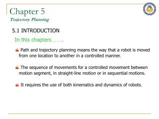
Chapter 5Trajectory Planning 5.1 INTRODUCTION In this chapters……. Path and trajectory planning means the way that a robot is moved from one location to another in a controlled manner. • The sequence of movements for a controlled movement between motion segment, in straight-line motion or in sequential motions. It requires the use of both kinematics and dynamics of robots.
Chapter 5Trajectory Planning 5.2 PATH VS. TRAJECTORY Path: A sequence of robot configurations in a particular order without regard to the timing of these configurations. Trajectory: It concerned aboutwhen each part of the path must be attained, thus specifying timing. Fig. 5.1 Sequential robot movements in a path.
Chapter 5Trajectory Planning 5.3 JOINT-SPACE VS. CARTESIAN-SPACE DESCRIPTIONS Joint-space description: - The description of the motion to be made by the robot by its joint values. - The motion between the two points is unpredictable. Cartesian space description: - The motion between the two points is known at all times and controllable. - It is easy to visualize the trajectory, but is is difficult to ensure that singularity. Fig. 5.3 Cartesian-space trajectory (a) The trajectory specified in Cartesian coordinates may force the robot to run into itself, and (b) the trajectory may requires a sudden change in the joint angles. Fig. 5.2 Sequential motions of a robot to follow a straight line.
Chapter 5Trajectory Planning 5.4 BASICS OF TRAJECTORY PLANNING Let’s consider a simple 2 degree of freedom robot. We desire to move the robot from Point A to Point B. Let’s assume that both joints of the robot can move at the maximum rate of 10 degree/sec. Let’s assume that both joints of the robot can move at the maximum rate of 10 degree/sec. Move the robot from A to B, to run both joints at their maximum angular velocities. After 2 [sec], the lower link will have finished its motion, while the upper link continues for another 3 [sec]. The path is irregular and the distances traveled by the robot’s end are not uniform. Fig. 5.4 Joint-space nonnormalized movements of a robot with two degrees of freedom.
Chapter 5Trajectory Planning 5.4 BASICS OF TRAJECTORY PLANNING Let’s assume that the motions of both joints are normalized by a common factor such that the joint with smaller motion will move proportionally slower and the both joints will start and stop their motion simultaneously. Both joints move at different speeds, but move continuously together. The resulting trajectory will be different. Fig. 5.5 Joint-space, normalized movements of a robot with two degrees of freedom.
Chapter 5Trajectory Planning 5.4 BASICS OF TRAJECTORY PLANNING Let’s assume that the robot’s hand follow a known path between point A to B with straight line. The simplest solution would be to draw a line between points A and B, so called interpolation. Divide the line into five segments and solve for necessary angles and at each point. The joint angles are not uniformly changing. Fig. 5.6 Cartesian-space movements of a two-degree-of-freedom robot.
Chapter 5Trajectory Planning 5.4 BASICS OF TRAJECTORY PLANNING Let’s assume that the robot’s hand follow a known path between point A to B with straight line. The simplest solution would be to draw a line between points A and B, so called interpolation. It is assumed that the robot’s actuators are strong enough to provide large forces necessary to accelerate and decelerate the joints as needed. Divide the segments differently. The arm move at smaller segments as we speed up at the beginning. Go at a constant cruising rate. Decelerate with smaller segments as approaching point B. Fig. 5.7 Trajectory planning with an acceleration-deceleration regiment.
Chapter 5Trajectory Planning 5.4 BASICS OF TRAJECTORY PLANNING Next level of trajectory planning is between multiple points for continuous movements. Stop-and-go motion create jerky motions with unnecessary stops. Blend the two portions of the motion at point B. Specify two via point D and E before and after point B Fig. 5.9 An alternative scheme for ensuring that the robot will go through a specified point during blending of motion segments. Two via points D and E are picked such that point B will fall on the straight-line section of the segment ensuring that the robot will pass through point B. Fig. 5.8 Blending of different motion segments in a path.
Chapter 5Trajectory Planning 5.5 JOINT-SPACE TRAJECTORY PLANNING 5.5.1 Third-Order Polynomial Trajectory Planning How the motions of a robot can be planned in joint-space with controlled characteristics. Polynomials of different orders Linear functions with parabolic blends The initial location and orientation of the robot is known, and using the inverse kinematic equations, we find the final joint angles for the desired position and orientation. First derivative of the polynomial of equation Initial Condition Substituting the initial and final conditions
Example • It is desired to have the first joint of a six-axis robot go from initial angle of 30o to a final angle of 75o in 5 seconds. Using a third-order polynomial, calculate the joint angle at 1, 2 3, and 4 seconds.
Chapter 5Trajectory Planning 5.5 JOINT-SPACE TRAJECTORY PLANNING 5.5.2 Fifth-Order Polynomial Trajectory Planning Specify the initial and ending accelerations for a segment. To use a fifth-order polynomial for planning a trajectory, the total number of boundary conditions is 6. Calculation of the coefficients of a fifth-order polynomial with position, velocity and a acceleration boundary conditions can be possible with below equations.
Chapter 5Trajectory Planning 5.5 JOINT-SPACE TRAJECTORY PLANNING 5.5.3 Linear Segments with Parabolic Blends Linear segment can be blended with parabolic sections at the beginning and the end of the motion segment, creating continuous position and velocity. Acceleration is constant for the parabolic sections, yielding a continuous velocity at the common points A and B. Fig. 5.13 Scheme for linear segments with parabolic blends.
Chapter 5Trajectory Planning 5.5 JOINT-SPACE TRAJECTORY PLANNING 5.5.5 Higher Order Trajectories Incorporating the initial and final boundary conditions together with this information enables us to use higher order polynomials in the below form, so that the trajectory will pass through all specified points. It requires extensive calculation for each joint and higher order polynomials. Combinations of lower order polynomials for different segments of the trajectory and blending together to satisfy all required boundary conditions is required.
Chapter 5Trajectory Planning 5.6 CARTESIAN-SPACE TRAJECTORIES Cartesian-space trajectories relate to the motions of a robot relative to the Cartesian reference frame. In Cartesian-space, the joint values must be repeatedly calculated through the inverse kinematic equations of the robot. Computer Loop Algorithm (1) Increment the time by t=t+t. (2) Calculate the position and orientation of the hand based on the selected function for the trajectory. (3) Calculate the joint values for the position and orientation through the inverse kinematic equations of the robot. (4) Send the joint information to the controller. (5) Go to the beginning of the loop