Download
1 / 22
220 likes | 241 Views
Explore GEANT simulations, track reconstruction, background rates for the Super-Bigbite Spectrometer Project, featuring experiments, configurations, and efficiency studies.

E N D
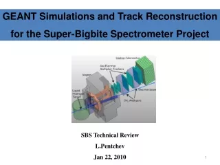
GEANT Simulations and Track Reconstruction for the Super-Bigbite Spectrometer Project SBS Technical Review L.Pentchev Jan 22, 2010
Outline • GEANT simulations of GEp(5) background and GEM photon detection efficiency • Experimental verification of MC simulations • Description of track search algorithm • Efficiency of the track reconstruction
GEANT3 Simulations of Background Rates • GEANT3 code with 100 keV threshold for tracking • Model includes the target, scattering chamber, magnet, SBS detectors (with COMPASS type GEM), BigCal, beamline, beam dump • Several configurations were studied: • Target only • Target + scattering chamber • + magnet, field clamps, lead shielding • + beam line and beam dump
GEANT3 Simulations of Background Rates • Low energy (<1 GeV) charged particles swept out by the magnet: • rates on First Tracker dominated by photon flux • rear tracker rates dominated by e- produced by photons in analyzers • Two-step simulations for photons: • Determine GEM photon detection efficiency • Particle flux and energy spectrum ( photon, electrons …) 4
GEM Photon Detection Probability Photon Energy, MeV • Separate g efficiency study by E.Cisbani using Geant4 with 10 keV threshold for tracking • “standard” COMPASS-type GEM Photon spectrum on front GEM chamber From GEANT3 • Material thickness (~photon eff.) has been reduced by about 30% compared to COMPASS GEMs for following analysis 5
MC Background Results: First GEM chamber • Initial soft electrons swept by the magnet • Photons originate from the target or from electrons hitting material in front of the magnet First GEM chamber:
Background Rates Summary For full configuration of GEp(5): 2nd tracker CH2 CH2 1st tracker 3rd tracker Coordinate Detector Al absorber BigCal
MC and Experimental Background Rate Comparison • Transversity Experiment E06-010 • 5.9 GeV beam, BigBite at 300, • 40cm3He polarized target • 3 MWDC behind the BigBite magnet • Luminosity from H2: 1.5 1036 cm-2 s-1; • 11.8 mAcurrent • GEANT3 Calculation • Simplified target description • 100 keV threshold • Hadron rates from DINREG Incremental MWDC rate from H2 : • 20% of rate for filled target configuration are “room” background • MC explains 80% of the experimental rates • This is encouraging level of agreement • Measurement with simpler target geometry, GEM detector and sweeping magnet will provide even better confidence in MC
Tracking Detector Configuration Lead (X,Y) x2 (U,V) x2 (X,Y) x2 (U,V) x2 (X,Y) x2 (X,Y) x2 CH2 CH2 HCAL (U,V) x2 1st tracker 2nd tracker 3rd tracker (X) x2 Al absorber BigCal
Track Reconstruction: Step 1 • From the hit on BigCal, reconstruct e- angles • Assume elastic kinematics to predict p angles and position on front chamber 3rd MC for elastic events 2nd 1st tracker p e BigCal beam
Track Reconstruction: Step 1 • BigCal hit constrains proton search region to 18 * 0.2 cm2 (x * y) and 30 * 0.7 mrad2 (Qx * Qy) Top View
Track Reconstruction: Step 2 • Tracking in First Tracker: • Find hits in 1st chamber within search region • For each hit by using angular constraints identify new smallersearch regionon next GEM chamber • Search regions defined by +/- 3s • Correlations bewteen (x,y) or (u,v) amplitudes taken into account based on COMPASS results: 30% of the hits pass the correlation requirement
Track Reconstruction: Step 3 • Proton is likely to be scattered only once, in first or second analyzer • HCAL + front tracker constrains 75 cm2search region in 3rd tracker 13
Track Reconstruction: Step 4 • Front and 3rd tracker constrain the search region in the 2nd tracker to 2 x 0.9 cm2 areas
Track Reconstruction Inefficiency Summary • Basic track reconstruction strategy is robust • Track inefficiency is due to detection inefficiency and the existence of “pseudo-tracks” • Probability of pseudo-tracks is reduced by redundancy of GEM planes • Events are rejected if any ambiguity exists • Total loss of events due to initial pseudo-track < 5% Using simulated full setup rates and combinatorial calculations:
What if we demand that the tracks are straight? • This additional filter reduces number of pseudo-tracks by factor of 5 in front tracker (assuming 150 mm resolution) • Chi-squared analysis shows: Future steps: Full MC data simulation including dead zones, amplitude distribution of signals
Summary • MC demonstrates that rates are well below the maximum capability of GEMs • The trackers are capable of operation at projected luminosity with 5% losses due to pseudo-tracks • Presently, there is agreement at 20% level, between MC and experimental rates in a BigBite experiment • Additional experimental studies and MC simulations will be performed
GEANT simulations of background rates: geometry • Geometry used for the simulations: • 40 cm LH target 40 cm with 0.1 mm Al walls and 50 um end caps • Scattering chamber with 0.5 mm kapton window • Magnet with field clamps and Pb shielding around magnet entrance • Beam line: +/- 25 mr opening, 8” Pb shielding at magnet exit • Main magnetic field and fringed fileds including the beam line in the magnet (approximated with constant field volumes) • SBS trackers, analyzers and HCAL; ½” Pb absorber in front of first analyzer (not shown) • Electron arm: BigCal with 20 cm Al shielding and tracking detector in front (not shown) • Beam dump: 5 m inside dump tunnel, f30 cm Be window and diffuser: 1” Al plate (not shown)
Track reconstruction: tracking inefficiency Pseudo – track probability per event represents tracking inefficiency: totaling 5 %