Download
1 / 27
270 likes | 294 Views
L1Calo Phase-1 architechure. Phase-1 Overview CTP upgrade status Include muon ROIs? CMM++ design Real-time data path + readout TP design Infrastructure + RTDP + readout L1Calo - CTP interface. Readout. to ROIB/DAQ. Global Merger. E/ g t /had clusters (CP). Pre- Processor (PPr).

E N D
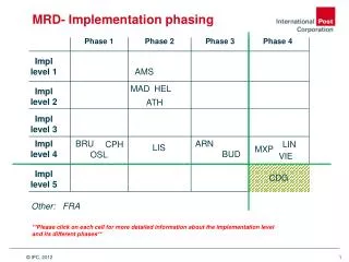
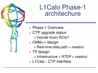
L1Calo Phase-1 architechure • Phase-1 Overview • CTP upgrade status • Include muon ROIs? • CMM++ design • Real-time data path + readout • TP design • Infrastructure + RTDP + readout • L1Calo - CTP interface
Readout to ROIB/DAQ Global Merger E/gt/had clusters (CP) Pre- Processor (PPr) Jet / SET (JEP) Analog tower sums (0.1 x 0.1) 0.2 x 0.2 Phase-1 upgrade (Muon ROIs?) 0.1 x 0.1 To CTP Cluster ROIs Jet ROIs High-speed fiber links
CTP upgrade studies • More algorithms require more CTP inputs • CTP can modify firmware to run at higher speed, multiplex inputs to accommodate more bits • Possibility to send muon ROIs from MUCTPI to our topological processor • Described in TDAQ week talk by Stefan Haas
CTP upgrade status (S. Haas) 124 Trigger inputs • Modified firmware tested successfully on CTP reference system • Clock phase scan shows good timing margins • Valid data window 65-70% (8-9 ns) of the bit period (12.5 ns) • Costs: reduced flexibility, 2-3 extra BCs of latency
MUCTPI upgrade (S. Haas) • MUCPTI receives muon candidates from 208 trigger sectors • Up to 2 muon candidates/sector/BC • Muon candidate consists of pT and location information (RoI) • MUCTPI now sends multiplicity per pT threshold to CTP • Detailed muon ROIs sent to LVL2 and DAQ at L1A rate • Topological trigger could potentially profit from muon RoI information
MUCTPI (S. Haas) We need to keep open the possibility for accepting/using muon ROIs in the TP • CTP may have to modify MIOCTs for additional RPC chambers in the ATLAS feet region • Requires 14 inputs per octant • Might allow opportunity to add muon ROIs to topological trigger!
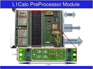
CMM++ design concept Glink DAQ/ROI readout on legacy RODs Glink SNAP12 Collect ROI coordinates from processor modules via backplane (4x speed) Up to three 12-fiber bundles 6.4 Gbit/s/fiber (can mount either Tx or Rx) Xilinx Virtex 6 XCE6VLX500T FF1759 840 I/O, 36 GTX transceivers SNAP12 SNAP12 LVDS cable outputs to CTP (legacy interface)
SNAP12 SNAP12 SNAP12 SNAP12 SNAP12 SNAP12 SNAP12 SNAP12 SNAP12 SNAP12 SNAP12 SNAP12 SNAP12 SNAP12 SNAP12 SNAP12 SNAP12 SNAP12 Staging: "Day-1" running Fan-in fiber patch cable X 2 CP 0 Jet 0 4 CP 1 12 40 Mbit/s 4 40 Mbit/s CP 2 4 Jet 1 CP 3 40 Mbit/s 12 To CTP To CTP
SNAP12 SNAP12 SNAP12 SNAP12 SNAP12 SNAP12 SNAP12 SNAP12 SNAP12 SNAP12 SNAP12 SNAP12 SNAP12 SNAP12 SNAP12 SNAP12 SNAP12 SNAP12 Stage 2: ROIs from CPM/JEP CP 0 Jet 0 4 CP 1 12 160 Mbit/s 4 160 Mbit/s CP 2 4 Jet 1 CP 3 160 Mbit/s 12 Day-1 algorithms on full ROI map To CTP To CTP
SNAP12 SNAP12 SNAP12 SNAP12 SNAP12 SNAP12 SNAP12 SNAP12 SNAP12 SNAP12 SNAP12 SNAP12 SNAP12 SNAP12 SNAP12 SNAP12 SNAP12 SNAP12 Stage 2a (optional) : Topological triggers using CMM++ CP 0 Jet 0 4 CP 1 12 4 160 Mbit/s 4 160 Mbit/s CP 2 4 4 4 Jet 1 CP 3 160 Mbit/s 12 12 To CTP To CTP JEP1 sees reduced ROI map from CP
SNAP12 SNAP12 SNAP12 SNAP12 SNAP12 SNAP12 SNAP12 SNAP12 SNAP12 SNAP12 SNAP12 SNAP12 SNAP12 SNAP12 SNAP12 SNAP12 SNAP12 SNAP12 Stage 3: Parasitic TP running X 2 CP 0 Jet 0 4 CP 1 12 160 Mbit/s 4 To TP 160 Mbit/s CP 2 4 Jet 1 To TP CP 3 To TP 160 Mbit/s 12 To TP To CTP To CTP Continue Day-1 algorithms
SNAP12 SNAP12 SNAP12 SNAP12 SNAP12 SNAP12 SNAP12 SNAP12 SNAP12 SNAP12 SNAP12 SNAP12 SNAP12 SNAP12 SNAP12 SNAP12 SNAP12 SNAP12 Stage 4: full TP running X 2 CP 0 Jet 0 CP 1 160 Mbit/s To TP 160 Mbit/s CP 2 Jet 1 To TP To TP CP 3 160 Mbit/s To TP Duplicate cables to multiple TP modules
CMM++ readout • Original idea: 2 Glinks • Either original components, or emulate in FPGA • Use existing RODs • ROI readout ~ same length • But DAQ links need to read out 4x as much input data • 35 ~97 ticks/time slice • Does this limit our readout capacity? • To increase r/o rate to DAQ: • Use 2 or more Glink outputs for DAQ r/o • Build more RODs? Glink Glink SNAP12 Virtex 6 SNAP12 SNAP12 13
RODs for CMM++ readout • Option 1: use one of our spare RODs to read out 10 extra CMM++ Glinks • Spare situation? • Option 2: Make more copies of current ROD • Easy to integrate • Old components • hard to find/replace • Option 3: new RODs? • Similar architecture but newer components (easier to port firmware/software) 14
Topological processor module Optical links bring L1 ROIs data to each TPM Data preprocessed at quadrant level. Global processing of selected results Scalable: upstream replication of input signals multiple modules can run in parallel each TPM has access to full data. FPGA (Global) FPGA FPGA FPGA FPGA Control Monitoring TTC DCS DAQ Interfaces Readout interface Optical links Quadrant merging OPTO OPTO OPTO OPTO OPTO To CTP OPTO OPTO OPTO DAQ OPTO OPTO ROI OPTO OPTO
Bringing muon ROIs to TP • MUCTPI has 16 MIOCTs • Each with ca 4 12 ROI positions (TGC coverage < 2.4) • 6 thresholds per ROI (encode in 3b) 144 bits/MIOCT/BC • 6.4 Gb/sfiber links 128 data bits/fiber/BC • Need 2 fibers / MIOCT to each TP module • So one TP quadrant would receive 40 fibers • 12 EM • 12 Tau • 8 Jet (Each JEP crates covers 2 quadrants per JEP) • 8 muon (4 MIOCTs per quadrant)
Fitting into Virtex-6 FPGAs? • Virtex-6 LXT (Began shipping in March 2009) • Up to 36 GTX transceivers @ 6.4 Gbit/s each • Cannot bring 40 fibers to a single FPGA • which we would prefer for quadrant level merging • Virtex-6 HXT (samples just shipping now) • Up to 48 GTX transceivers @ 6.4 Gbit/s each • Up to 24 HTX tranceivers @ >11 Gbit/s each • HX565T has 40 GTX transceivers • But....expensive and new (long lead time?) 17
LXT vs HXT solutions LXT only LXT + HXT 18
TP module readout Input data: 1536 bits / BC / CMM++ 10 144 bits / BC / MIOCT 16 Total: 17,664 bits/BC Output data: ~200 bits/BC? Readout must handle ~18,000 bits/BC! Equivalent of more than 20 G-links per TP module! We almost certainly need a new kind of ROD 19
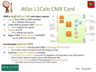
TP ROD Option 1: TP module sends readout to external ROD crate Use multi-Gbit optical links from TP module to ROD but FPGA transceivers already needed as inputs! Option 2: TP ROD on rear transition module Option 3: TP module is its own ROD Note: rear transition module probably needed for Slink and CTP outputs, anyway (front panel full!) 20
TP and rear transition modules FPGAs 3 CTP output ROD Readout links Input links 2 1 backplane zones
Other TP infrastructure Crate/backplane/power Crate controller "TCM-like" interface TTC distribution CAN/DCS interface 22
L1Calo - CTP interface Current interface: 6 direct LVDS cables from CMMs to CTP Transitional interface: 6 outputs from CMM++ plus several output cables from n TP modules Final phase-1 interface: Some number of output cables from some number of TP modules In other words, the L1Calo-CTP cabling will change over time! Option 1: Re-cable each time we change things Option 2: Build "active patch panel" to remap trigger bits to same set of CTP input cables 23
Active patch panel (conceptual) From CMM++ modules Ethernet TTC DCS/Can Router FPGA To CTP readout link(s) From TP modules
Active patch panel functions Basic function: Remap L1Calo outputs and send to CTP inputs Diagnostic functions: Capture, read out and histogram all L1Calo output bits, even those not yet sent to the CTP (useful for parasitic testing of new triggers) Custom, flexible rate monitoring Augment/extend CTP capabilities? Offload some L1Calo/muon trigger processing to the active patch panel's FPGA if needed. 25
Summary: Phase-1 hardware work CMM++ 9U ROD for CMM++ readout Topological processor TP module Crate infrastructure Controller TP-TCM TP-ROD CTP interface (active patch panel?) Plus... Test infrastructure (DSS) New fiber cable plant 26
Plus lots of firmware! JEM/CPM (add ROIs to RTDP) CMM++ Day-1, Phase 1-4, etc. CMM++ ROD Either updated 9U ROD or new module Topological processor module TPM ROD CTP interface Anything I've missed? 27