Effective Process Modeling Techniques for Systems
140 likes | 213 Views
Learn about logical and physical models, differences between DFDs and flowcharts, structured analysis diagrams, and when to draw process models. Get insights on modern structured analysis practices.

Effective Process Modeling Techniques for Systems
E N D
Presentation Transcript
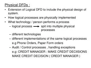
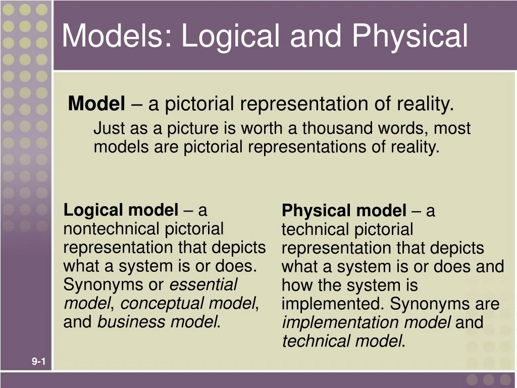
Logical model – a nontechnical pictorial representation that depicts what a system is or does. Synonyms or essential model, conceptual model, and business model. Physical model – a technical pictorial representation that depicts what a system is or does and how the system is implemented. Synonyms are implementation model and technical model. Models: Logical and Physical Model – a pictorial representation of reality. Just as a picture is worth a thousand words, most models are pictorial representations of reality.
Differences Between DFDs and Flowcharts • Processes on DFDs can operate in parallel (at-the-same-time) • Processes on flowcharts execute one at a time • DFDs show the flow of data through a system • Flowcharts show the flow of control (sequence and transfer of control) • Processes on a DFD can have dramatically different timing (daily, weekly, on demand) • Processes on flowcharts are part of a single program with consistent timing
Types of Logical Processes Function – a set of related and ongoing activities of a business. • A function has no start or end. Event – a logical unit of work that must be completed as a whole. Sometimes called a transaction. • Triggered by a discrete input and is completed when process has responded with appropriate outputs. • Functions consist of processes that respond to events. Elementary process – a discrete, detailed activity or task required to complete the response to an event. Also called a primitive process. • The lowest level of detail depicted in a process model.
When to Draw Process Models • Strategic systems planning • Enterprise process models illustrate important business functions. • Business process redesign • “As is” process models facilitate critical analysis. • “To be” process models facilitate improvement. • Systems analysis (primary focus of this course) • Model existing system including its limitations • Model target system’s logical requirements • Model candidate technical solutions • Model the target technical solution
Modern Structured Analysis(More Commonly Practiced) • Draw context DFD to establish initial project scope. • Draw functional decomposition diagram to partition the system into subsystems. • Create event-response or use-case list for the system to define events for which the system must have a response. • Draw an event DFD (or event handler) for each event. • Merge event DFDs into a system diagram (or, for larger systems, subsystem diagrams). • Draw detailed, primitive DFDs for the more complex event handlers. • Document data flows and processes in data dictionary.
SoundStage Functional Decomposition Diagram • Break system into sub-components to reveal more detail. • Every process to be factored should be factored into at least two child processes. • Larger systems might be factored into subsystems and functions.