Download
1 / 35
390 likes | 628 Views
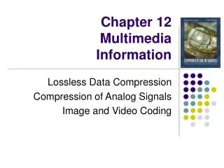
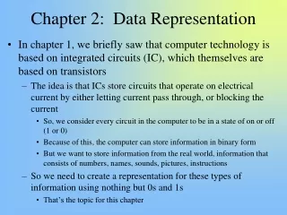
Chapter 2 Multimedia Information Representation. 2.1 Introduction 2.2 Digitization Principles 2.3 Text 2.4 Images 2.5 Audio 2.6 Video. Contents. 2.1 Introduction. Codeword : a fixed number of bits representing a set of symbols, e.g) ASCII Code, FAX Run-length Code, … .

E N D
Chapter 2 Multimedia Information Representation • 2.1 Introduction • 2.2 Digitization Principles • 2.3 Text • 2.4 Images • 2.5 Audio • 2.6 Video Contents
2.1 Introduction • Codeword: a fixed number of bits representing a set of symbols, e.g) ASCII Code, FAX Run-length Code, … . • Signal Encoder • Signal Decoder • CODEC performs the conversion using some codewords Audio-Video CODEC (Coder-Decoder) Data Data Network Host Host conversion conversion conversion conversion Data (or Signal) Signal (or Data) Data (or Signal)
2.2 Digitization Principles (1)(Analog Digital) terms - Spectrum VS. Bandwidth - Signal bandwidth VS. Channel (Bandlimiting) bandwidth - Cutoff frequency = min {Signal bandwidth, Bandlimiting bandwidth} Analog Digital D/A Converter A/D Converter Bandlimiting Filter Sampler Quantizer & Coder Decoder Lowpass Filter Digital Analog Networks Host Decoder Host Encoder conversion conversion Transfer
Encoder Analog input signal Bandlimiting filter Sampler (sample-and-hold) Quantizer Encoder PCM procedure 대역 제한 필터 clock 표본화 양자화 부호화 A B D E F C time A B Network C Decoder D 7 4 3 5 DAC Lowpass filter 0 E -4 -5 -3 DA 변환 저 대역필터 G H 0 000 0 100 0 111 0 011 1 100 1 101 1 011 0 101 F Analog output signal G 0 101(1-bit sign & 3-bit amplitude magnitude) H
2.2 Digitization Principles(2)(Analog Digital) • Analog Signal • Bandwidth, BHz, via bandlimiting channel (see the next slide) • Encoder • Bandlimiting filter • Sampling: 2Bsps(samples per sec) aliasing may happen ! • Quantizing: Aliasing filter for eliminating alias signals • quantization interval q = 2(Vmax/2n) • quantization error/noise = q/2 • Decoder • low-pass filter (= bandlimiting filter = anti-aliasing filter) Dynamic range of signal D D=20 log10(Vmax/Vmin) n: # of bits Vmax: max(min) positive (negative) signal amplitude
2.2 Digitization Principles (3)(Analog Digital) Aliasing signal & its elimination When does aliasing occur ? If the sampling rate is lower than the Nyquist rate 6KHz real signal 2KHz alias signal because of T’ = 3T T amplitude time 6KHz sine-wave is sampled at 8Ksps, lower than the Nyquist rate 12Ksps(26KHz) T’ = 3T 8Ksps All frequency components in the source signal that are higher in frequency than half the sampling frequency being used will generate related lower-frequency alias signal which will simply add to those making up the original thereby causing it to become distorted Conclusion Using “bandlimiting filter”, let’s pass only those Frequency components up to that determined by the Nyquist rate Resolution bandlimiting filter = anti-aliasing filter = low-pass filter = reconstruction filter
2.2 Digitization Principles (4)(Analog Digital) • Example 2.2 An analog signal has a dynamic range of 40 dB. Find the magnitude of the quantization noise relative to the minimum signal amplitude if the quantizer uses 1) 6 bits and 2) 10 bits • Solution It follows that 40 = 20 log10(Vmax/Vmin) by assumption and finally the equation 102 = Vmax/Vmin results in Vmin = Vmax/100 And the quantization noise is determined by q/2 where, q is the quantization interval given by q =2(Vmax/2n). Thus q/2= Vmax/2n. For n =6, q/2= Vmax/2n(= Vmax/64) >Vmin(=Vmax/100) unacceptable ! For n =10, q/2= Vmax/2n(= Vmax/1024) <Vmin(=Vmax/100) acceptable !
dB (decibel) : The decibel measures the relative strength of two signals or a signal at two different points p1 and p2 given by dB = 10 log10(p2/p1) dB decibel If a signal power is reduced to half at p2 such that p2=p1/2 10 log10(p2/p1) = 10 log10(0.5p1/p1)= 10 log10(1/2) = 10 log101- 10 log102= -3dB p2 p1 irritating
2.3 Text • Unformatted Text, Plaintext • String of fixed-size characters • ASCII, Mosaic Characters, … . • Formatted Text • String of characters of different sizes, styles & shapes with table, figures (graphics) & images • Latex, Acrobat, … . • Hypertext • Integrated set of documents comprising formatted & unformatted texts with linkages • among them • HTML, Postscripts, SGML, … . Well-defined code-words are used for Text Creation & Manipulation
2.4 Images • Image (still picture) Classification • Computer-generated images (computer graphics) e.g) palette files • Digitized images of documents and/or pictures e.g) fax-scanned files, scanned color-image files • Graphics • high-level language form: description of attributes of objects • bit-map form: actual pixel-images • gif: graphical interchange format • tiff: tagged image file format • srgp: simple raster graphics package • Digitized Documents • Facsimile (FAX) machine, about 2Mbits/page(black-white/pixel) • Pixel resolution: 8 per mm • Line resolution: 3.85 or 7.7 per mm(100 or 200 lines per inch) VGA 640 480 (=열수 행수) pixels 8-bits/pixel pixel (or pel): picture element
Digitized Pictures(1) pixel depth: # of bits per pixel • m-bit per pixel (pixel depth m) • good-quality black-white picture: 8-bit/pixel(256 gray levels) • colored-picture: 24-bit/pixel(R/G/B each 8-bit yielding 16 M colors) • Coloring Principles : How is color produced and represented ? • Color gamut(색상범위 색대역): a whole spectrum of colors • Three primary colors(삼원색): R (Red), G (Green), B (Blue) • all kind colors are produced by using different proportions of these primary colors • Additive Color Mixing (가산혼합) on a black surface • Subtractive Color Mixing (감산혼합) on a white surface • Raster-Scan Principles: TV Screen or Computer CRT Monitor • NTSC (National Television Standards Committee)-USA • 525(active 480) lines/frame & 60-time refresh rate/sec • PAL (Phase Alternation Line)/CCIR/SECAM • 625(active 576) lines/frame & 50-time refresh/sec 참고 하기1 참고 하기2
1 2 3 4 5 N 1 2 3 M Digitized Pictures(2) Scanning Order Sweep TV 1. N=525(NTSC) & 625(PAL/SECAM/CCIR) 2. fresh rate (Hz) = 60(NTSC) & 50(PAL/SECAM/CCIR) 3. M is determined by the aspect ratio (see the next slides) frame : a complete set of N horizontal scan lines frame refresh rate: # of frames per sec at least 50 Hz to avoid flickering Retrace M x N 행렬 Scanning Method 60 or 50 Hz refresh rate Progressive scanning : 123…N: one frame (전진주사) Interlaced scanning : 135…N-1: first half frame (field) (격월주사) 246…N: 2nd half frame (filed) 30 or 25 Hz refresh rate
Digitized Pictures(3) in HTML • Raster-Scan Principles • Raster(래스터): a finely-focused electro beam • Phosphor(발광체): a light-sensitive material that emits light when energized • white-sensitive phosphor: a single electron beam used • color-sensitive phosphor : each pixel comprises a set of three color-sensitive phosphors, one each for R, G, B signals, called phosphor triad • beam signal may be eitheranalog or digital form • Pixel Depth: # of bits per pixel • CLUT (Color Look-Up Table): 24-bit/pixel yields 224 colors. But eye discriminates between some ranges of colors hence, each pixel value is used as an index on CLTT of 256 colors (compression achieved !) #FFFFFF spot size: 0.635mm(0.025inch)
Digitized Pictures(4) • Aspect Ratio: ratio of the screen width to the screen height • NTSC, 525 scan lines/frame ⇒ 480(45) data (control) lines • 4/3 aspect ratio ⇒ 480 4/3(=640) pixels/line • 16/9 aspect ratio ⇒ 480 16/9(=853.33) pixels/line • PAL/CCIR/SECAM 625 lines/frame ⇒ 576(49) data (control) lines • 4/3 aspect ratio ⇒ 576 4/3(=768) pixels/line • 16/9 aspect ratio ⇒ 576 16/9(=1024) pixels/line Representing an MN pixels under a particular aspect ratio Computer Graphics Array standard resolution #of colors Bytes/frame VGA 640 x 480 x 8 256 307.2K XGA 640 x 480 x 16 1024 x 768 x 8 64K 256 614.4K 786.432K SVGA 800 x 600 x 16 1024 x 768 x 8 1024 x 768 x 24 64K 256 16M 960K 786.432K 2359.296K refresh rate: 50-70Hz
Digitized Pictures • DVI (Digital Visual Interface) 기존 그래픽 카드에는 램댁(RAMDAC)이 들어있어 디지털 신호를 아날로그 신호로 바꾸어 화면을 표시함. 기존 CRT모니터가 아날로그 방식이기 때문임. 그러나 LCD는 완전 디지털이기 때문에 굳이 아날로그로 변경할 이유가 없기 때문에 DVI단자를 만들어 디지털로 바로 전송하게 하는 것임.
Digitized Pictures(5) • Example 2.3 Derive the time to transmit the following digitized images at both 64Kbps and 1.5Mbps networks • a 6404808 VGA-compatible image • a 102476824 SVGA-compatible image • Solution The size of each image in bit is as follows • a VGA image = 6404808 = 2.46Mbits • an SVGA image = 102476824 =18.88Mbits The time to transmit each image is given as follows • at 64Kbps : VGA = 2.46Mbits/64Kbps = [2.46106]/[64 103] = 38.4 sec. SVGA = [18.88106]/[64 103] = 295 sec. • at 1.5Mbps: VGA = 2.46Mbits/1.5Mbps = [2.46106]/[1.5 106] = 1.64 sec. SVGA = [18.88106]/[1.5 106] = 12.59 sec.
Digitized Pictures(6) • Digital Cameras & Scanners • (Still image cameras) 2-D grid of photo-sites (빛 감지 diode), light-sensitive cells, made of charge-coupled devices (CCD’s) • level of light intensity on each photosites is converted into a digital value using an AD converter when the shutter is activated • (Scanners) single-row of photo-sites is exposed in time- sequence with the scanning operation • How are color images obtained ? • each photosite/pixel is coated with R/B/G filter & the color is determined by the level of it together with 8 neighbors in a 3 x 3 grid structure • use of three separate exposures of a single photosite, say, first R filter, 2nd G filter, and finally B filter • use of three separate image sensors per pixel • e.g) TIFF (tagged image file format), TIFF/EP for electronic photography General consumer Photo studio professional
2.5 Audio • Typical Audio Types • Speech signal for interpersonal application such as (video) telephony • Music-quality audio such as CD-on-demand & broadcast TV • synthesizer • microphone • loudspeaker Basics on Audio Signals • Human speech: 50Hz -10KHz (4Khz in a plain-old-telephone system) • - 2 x 10K or 2 x 8K sps monaural (mono) speech • - (2 x 10K) x 2 or (2 x 8K) x 2 sps stereophonic speech • - ideally, 12 bits/sample • 2.Human audible music: 15Hz - 20KHz • - 2 x 20K sps monaural (mono) music • - (2 x 20K) x 2 sps stereophonic music • - ideally, 16 bits/sample sps: samples per sec.
PCM Speech(1) • Human Voice over PSTN • 200Hz-3.4Khz bandlimiting channel: about less than 4Khz • 8K(2x4K) sps, 8bits/sample : ITU-T G.711(PCM) recommendation • Companding (compressing/expanding) • 1-bit: polarity, 3-bit: segment code, 4-bit: quantization code Pure PCM signals Compander (compressor/expander) Enhanced PCM signals Equal (linear) interval quantization & same level of quantization error Non-linear (unequal) interval quantization & narrower intervals for smaller amplitude signals Irrespective of the magnitude of the input signal , the same error level for both low (quiet) signals and high (loud) signals is produced Why companding ? Because the human ears are more sensitive to noise on quiet signals than it is on loud signals. Hence the effect of quantization noise (error) can be reduced with companding
PCM Speech(2) • Companding Example: 5-bit per sample(1-bit polarity, 2-bit segment code, & 2-bit quantization code) compressing +V signal Linear quantization intervals 11 10 01 00 11 11 10 01 00 10 Segment codes(+) Polarity: 1 11 10 01 00 01 11 10 01 00 00 -V 00 01 10 11 +V 00 00 01 10 11 Narrower intervals for smaller amplitude 01 Polarity: 0 Segment codes(-) 00 01 10 11 10 00 01 10 11 11 -V
PCM Speech(3) • Companding Example: 5-bit per sample(1-bit polarity, 2-bit segment code, & 2-bit quantization code) Expanding +V signal Linear quantization intervals 11 10 01 00 11 11 10 01 00 10 Segment codes(+) Polarity: 1 11 10 01 00 01 11 10 01 00 00 00 01 10 11 00 00 01 10 11 Wider intervals for smaller amplitude 01 Polarity: 0 Segment codes(-) 00 01 10 11 10 00 01 10 11 11 -V
PCM Speech(4) • Two Companding Codewords for PCM • μ-law: North America & East Asia • A-law: Europe “Signed & magnitude” representation μ-law A-law +127 +96 +64 +32 +0 -0 -32 -64 -96 -127 1 0000000 1 0011111 1 0111111 1 1011111 1 1111111 0 1111111 0 1011111 0 0111111 0 0011111 0 0000000 1 1111111 1 1100000 1 1000000 1 0100000 1 0000000 0 0000000 0 0100000 0 1000000 0 1100000 0 1111111 1’s complement Sign bit (polarity)
CD-Quality Audio • Human audible bandwidth: 15Hz-20Khz 40Ksps • In CD-ROMs, more higher, say, 44.1Ksps & 16-bit/sample used • bit rate for channel = sampling rate x bits per sample = 44.1 x 103 x 16 = 705.6 Kbps • total rate required for stereophonic music = 2 x 705.6 = 1.411 Mbps • storage capacity for a 1 hour CD-ROM title = 1.411 x 60 x 60 = 634.95 Mbytes this takes (634.95 x 106 x 8)/(10 x 106) = 8.5 min. down-loading time via a 10Mbps link network !
Synthesized Audio • A digitized audio requires a large amount of memory while a synthesized audio is 1)2 or 3 orders of magnitude less2) much easier to edit & to mix several passes together • An audio/sound synthesizer: computer + keyboard + a set of sound generators + interfaces for instruments (elec. guitar) * MIDI (Music Instrument Digital Interface): Standard I/O interfaces • Messages (status byte + data bytes) • Connectors, Cables, & Electrical Signals
2.6 Video (Motion): Broadcast TV Video Applications • Entertainment: Broadcast TV, VCR/DVD Recordings • Interpersonal: Video Telephony & Videoconferencing • Interactive: Video Clips on PC Windows • Scanning Sequences: Interlaced Scanning • To minimize the amount of tx bandwidth, a frame is divided into two halves called fields e.g) 525-line 50-time frame refresh rate/sec. - 262.5 odd lines 50-time field rate/sec. - 262.5 even lines 50-time field rate/sec. • In reality, 525-line 25-time frame refresh rate/sec.
Broadcast TV(2) Luminance: 휘도 Brightness: 밝기 Hue (Tint): 색조/색상 Saturation: 채도 Chrominance: 색차 • Color Signals • Three properties of a color - Brightness, Hue (Tint) & Saturation • Color production: an equation of R, G, and B phosphors - 0.299 R + 0.587 G + 0.114 B where, 0.299+0.587+0.114=1 • Luminance refers to the brightness of a source, the hue & the saturation called, chrominancecharacteristics • say, luminance Ys =0.299 Rs + 0.587 Gs + 0.114 Bs • Ys: magnitude of luminance signal • Rs, Gs, Bs: magnitudes of three major colors • Two color difference signals: Blue chrominance Cb and Red chrominanceCr - Cb = Bs-Ys, Cr = Rs -Ys
Broadcast TV(3) • Chrominance Components • Composite Video Signal for Transmission • -Ys, Cb, and Crsignals are combined together and signal differences are scaled down before transmission • In PAL - Y = 0.299 R + 0.587 G + 0.114 B • U(Cb) = 0.493(B-Y) = -0.147R-0.289G+0.437B • V(Cr) = 0.877(R-Y) = 0.615R-0.515G-0.1B • In NTSC - Y = 0.299 R + 0.587 G + 0.114 B • I(Cb) = 0.74(R-Y)-0.27(B-Y) = 0.599R-0.276G-0.324B • Q(Cr) = 0.48(R-Y)+0.41(B-Y) = 0.212R-0.528+0.311B
Digital Video • Advantages of DV • Easy to store in computer • Easy to edit and integrate with other types • Easy to digitize three RGB component signals • The resolution of eyes are less sensitive for color than it is for luminance. Hence, two chrominance signals can tolerate a reduced resolution • Transmission bandwidth is achieved by using the luminance and two color difference signals, instead of the RGB signals directly. • CCIR-601 Recommendations: standard for the digitization of video pictures
Digital Video(2) Y • 4:2:2 format(CCIR-601) • Recommendation for use in TV studio • Three component (analog) video signals may have bandwidths • up to 6Mhz for the luminance ⇒ 12Mhz sps • less than 3Mhz for the two chrominance signals ⇒ 6 Mhz sps • In reality, 13.5M sps for luminance, 6.75 M sps for the two chrominance signals • In NTSC(525-line) system, total line sweep time 63.56μsec = retrace time 11.56 μsec + an active line sweep time 52 μsec • In PAL(625-line) system, total line sweep time 64μsec = retrace time 12 μsec + an active line sweep time 52 μsec Cb Cr Orthogonal sampling Line sampling rate: 5210-613.5106= 702 samples/line In reality, 720 samples/line Line sampling rate: 5210-66.75106= 351 samples/line In reality, 360 samples/line 4Y samples for every 2Cb and 2Cr samples(4:2:2)
Digital Video(3) PAL 625-line • 4:2:2 Format Bit Rate & Storage (NTSC 525-line) • The number of active (visible) lines: 480 • The number of samples per line: 720 • Resolution of luminance Y = 720480 Two chrominance signals Cb = Cr = 360480 • Line sampling rate: 13.5sps for Y & 6.75sps for both Cb & Cr • Bits per sample: 8 bits • Bit rate per line = 13.51068 + 2(6.751068) = 216Mbps • Bits per line = 7208 + 2(3608) = 11.52Kbits • Bits per frame = 48011.52 = 5.5296Mbits • Bits for 1.5 hrs Video assuming 60 refresh rate = 5.5296601.53600 = 223.9488GBytes 576 720 720576 360576 576 6.63555Mbits 6.6355550
Digital Video(4) • 4:2:0 Format • used in Digital Broadcast Applications • interlaced scanning with the absence of chrominance samples in alternative lines • 525-line system • Y = 720480(the same as 4:2:2 format), Cb = Cr = 360240 • 625-line system • Y = 720576, Cb = Cr = 360288 • bit rate per line: 13.51068 + 2(3.3751068) = 162Mbps • HDTV Format • used in High-Definition Television (four times bit rate) • 4/3 14401152 pixels(50/60 Hz refresh rate) & 16/9 wide-screen 19201152 pixels(25/30 Hz) with # of visible lines per frame 1080
Digital Video(5) • SIF (Source Intermediate Format), 4:1:1 Format • used in Video Cassette Recorders (VCRs) • progressive (non-interlaced) scanning since it is intended for storage applications • Half of 4:2:0 format: “Subsampling & Temporal Resolution” • 525-line system • Y = 360240, Cb = Cr = 180120 • 625-line system • Y = 360288, Cb = Cr = 180144 • bit rate per line • 6.751068 + 2(1.68751068) = 81Mbps
Digital Video(6) • CIF (Common Intermediate Format), 4:1:1 format • used in Video Conferencing applications • spatial resolution of the SIF 625-line system plus temporal resolution of the SIF 525-line system • Y = 360288, Cb = Cr = 180144 • refresh rate: 30 Hz • bit rate per line: 6.751068 + 2(1.68751068) = 81Mbps • many variants for videoconferencing using desktop PCs or ISDN/PSTN • say, typically 4 or 16 64Kbps channels used • 4CIF: Y = 720576, Cb = Cr = 360288 • 16CIF: Y = 14401152, Cb = Cr = 720576
Digital Video(7) • QCIF (Quarter CIF), 4:1:1 Format • used in Video Telephony applications • half spatial resolution of the CIF and either half or quarter temporal resolution of the CIF • Y = 180144, Cb = Cr = 9072 • refresh rate: 15 or 7.5 Hz • bit rate per line: 3.3751068 + 2(0.843751068) = 81Mbps • a lower version is typically used for single 64Kbps channel ISDN or PSTN with modems: sub-QCIF(SQCIF) • Y = 12896, Cb = Cr = 6448
Digital Video(8) • PC Video Digitization