Download
1 / 12
120 likes | 145 Views
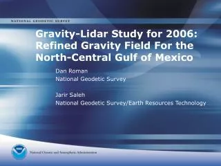
Gravity Lidar Study for 2006: A First Look. D.R. Roman, V.A. Childers, D.L. Rabine, S.A. Martinka, Y.M. Wang, J.M. Brozena, S.B. Luthcke, and J.B. Blair Canadian Geophysical Union 2006 Annual Meeting Banff, Alberta, Canada Geodesy and Geodynamics Session 15 May 2006. Background.

E N D
Gravity Lidar Study for 2006: A First Look D.R. Roman, V.A. Childers, D.L. Rabine, S.A. Martinka, Y.M. Wang, J.M. Brozena, S.B. Luthcke, and J.B. Blair Canadian Geophysical Union 2006 Annual Meeting Banff, Alberta, Canada Geodesy and Geodynamics Session 15 May 2006
Background • Second year of three year study of Gulf of Mexico • Funded & flown by NOAA using NRL’s gravity meter and NASA’s LVIS lidar • Collects aerogravity starting above stable onshore areas to deep offshore areas established by altimetry • Detects systematic errors in ship and terrestrial data • For southern Louisiana subsidence region, may be used to estimate effects of listric faulting (slumping) • Lidar will be used in conjunction with hyper-accurate regional tide models to check geoid and MDT models
Equipment • Aircraft: Cessna Citation II • NOAA AOC provided flight hours/crew • Dual GPS antennas and receivers • Independent antenna/receiver for each meter • Lacoste-Romberg Air-Sea Gravimeter II • Naval Research Lab equipment/personnel • First Applanix POSAV mounted to collect INS • Laser-Vegetation Imaging Sensor (LVIS) • NASA Remote Sensing Lab equipment/personnel • Second Applanix POSAV mounted to collect INS
Data Collection Parameters • Tracks should resolve gravity/geoid field to 20 km • Flights are at 35000 ft (10+ km) elevation • Track spacing is 10 km perpendicular to shoreline • Provides most of the signal • Avoids spectral aliasing • Cross-tracks at ~50 km parallel to shoreline • Speed over Ground is around 280 kts (500 kmh) • Along track filtering is expected to yield 20 km • Flight legs expected to be between 1-2 hours
Data Collection Process • Flight departures based on predicted PDOP spikes in GPS satellites and availability of restricted airspace • One hour prior to take off • prep ground GPS stations (replace batteries, etc.) • Spin up gravity meter/calibrate • Predetermine Eotvos correction for inflight • Load memory cards • During flight: • Calibrate LVIS in clear skies over open ocean • Minimize bank in turns for both meters
Data Collection Process (cont.) • Principal flight legs are 500 km long at 500 kmh • Take-off, line up for first run, fly one hour • Easy turn (Williamson) to minimize banking • One hour back up return leg then land • Most flights in around the three hour mark • While on ground for about an hour • Swap out batteries/memory cards • Keep GPS on! Both onboard and ground stations • Helps to calibrate the antennas later • If time, weather, and airspace access permit – do it again
J24 J22 J21 J20 J18 J14 J12 J11 M30 M28 M24 M22 M21 M20 M18 M14 M12 M11 J26 J25 J23 J19 J17 J16 J15 J13 M29 M27 M26 M25 M23 M19 M17 M16 M15 M13 J10 J9 J8 J7 J5 J4 J2 J1 M10 M9 M8 M7 M5 M4 M2 M1 J6 J3 M6 M3 T1 T2 T3 T4 T5 T6 T7 T8