Download
1 / 29
290 likes | 304 Views
Explore the benefits and applications of modular design in FPX systems, improving performance and flexibility. Learn about RAD FPGA logic resources, reconfiguration control, memory interfaces, and control cell processors.

E N D
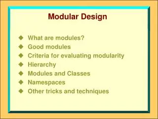
Overview • Motivation • RAD Logic Resources • RAD Infrastructure Modules • Reconfiguration Control • SRAM Interface • Control Cell Processor • RAD Module Interface • Top Level RAD Design • Pins and layout overview • Module instantiation
Motivation for Modular Design • Definitions • Modules: entities that perform network data processing • FPX Applications: packet classification, compression, etc. • Infrastructure: all other entities necessary for system functionality • Memory interfaces, control cell processor, reconfiguration control, etc. • Assume most applications do not need all available logic and memory resources • Higher performance and flexibility are achievable via multiple modules • Standard module interface • Ensures module interoperability • Reduces design redundancy • Shortens module design cycle
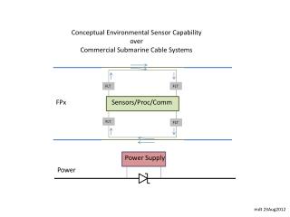
Dynamic Hardware Plugins (DHP) • Programmable router with software and reconfigurable hardware packet processing • Hardware plugins • Static interfaces for I/O and off-chip memory • User defined on-chip memory • Infrastructure • IOC • Slotted ring interface • Application Controller • Reconfiguration control • Memory Interfaces • SRAM/SDRAM interfaces • Applications • Position independent • Dynamically loadable • Prototype with WUGS/SPC/FPX • Partially reconfigure RAD FPGA for new applications
RAD FPGA Logic Resources • Virtex 1000E –7 FPGA • 4 Global Clock Trees • (2) 100MHz clocks from FPX board • Globally accessible IOBs • Versa-Ring routing • 3 flops for tri-state bussing • 64 x 96 CLB array • 2 flops/LUTs per Slice • 2 Slices per CLB • Total = 24,576 flops/LUTs • 96 Block SelectRAMs • 4096 bits per block • 6 columns of 16 blocks • 6 columns of dedicated interconnect • Total = 393,216 bits
Reconfiguration Control Module • Partial reconfiguration controller for RAD FPGA • Executes reconfiguration handshake with NID FPGA and RAD modules • Module interface • Localized synchronous reset • Enable • Ready
SRAM Interface Module • Interface to off-chip ZBT SRAM • Abstracts modules from device specific timing • Independent interface for each module • Arbitrates requests and issues grant to winning module • Modules retain access by holding request high after receiving grant • Modules responsible for preventing starvation
Control Cell Processor • Captures control cells for off-chip memory transactions • SRAM read/write • SDRAM read/write • Not yet implemented • Checks for correct HEC • VPI = 0x000 • VCI = 0x0023 (35) • Modifiable register • ModuleID = 0x00 • OpCodes • Even OpCodes for command cells • Response OpCode = 1+OpCode • OpCodes 0x00 to 0x0F reserved for common operations • Updates CRC for response cells
RAD Module Interface • Cell I/O and Flow Control • 32-bit wide UTOPIA-style interface w/ unique timing • Off-chip Memory Access • Arbitrated access to SRAM and SDRAM via standard interface • Control (clock, reset, and reconfiguration control)
Control Interface • 100MHz global clock (CLK) • All I/O signals should be synchronous to CLK • Synchronous reset (RESET_L) • Asserted low for 1 clock cycle • Reconfiguration handshake (ENABLE_L, READY_L) • Enable asserted low at reset • Module must pull READY_L high after reset, prior to accepting cells in order to prevent reconfiguration during operation • Enable asserted high prior to reconfiguration • Module stops accepting cells, flushes internal pipelines, and asserts READY_L for at least one clock cycle
Cell Input Interface • Start of Cell (SOC_MOD_IN) • Signals the first word of the ATM cell • 32-bit wide data path (D_MOD_IN) • ATM cells transferred as (14) 32-bit words • First word arrives with SOC_MOD_IN • Remaining 13 words arrive on subsequent clock cycles • Transmit Cell Available (TCA_MOD_IN) • Signals module’s ability to accept a cell • Must be valid 6 clock cycles prior to the last cycle of the current cell transfer
Cell Output Interface • Start of Cell (SOC_OUT_MOD) • Signals the first word of the ATM cell • 32-bit wide data path (D_OUT_MOD) • ATM cells transferred as (14) 32-bit words • First word sent with SOC_MOD_IN • Remaining 13 words sent on subsequent clock cycles • Transmit Cell Available (TCA_OUT_MOD) • Signals output’s ability to accept a cell • Modules must sample TCA_OUT_MOD no sooner than 3 clock cycles prior to asserting SOC_OUT_MOD
SRAM Interface • Arbitration Handshake • SRAM_REQ requests and holds memory access • SRAM_GR grants access and initiates access termination • Module may retain memory access for duration of transaction set • If grant is de-asserted, module must complete current transaction and release memory • Module is responsible for preventing starvation • Reads • Hold SRAM_RW high, issue address • Data appears inside module 6 clock cycles later • Writes • Assert SRAM_RW low, issue address and data • Data will be written 5 clock cycles later IMPORTANT: HOLD SRAM_RW HIGH TO PREVENT OVERWRITING VALID MEMORY DATA
SRAM Interface Timing • All I/O signals must be flopped at module boundary to ensure timing constraints are met • Timing diagrams take reference point from inside module and assume boundary flops
RAD Pin Mappings Input Output Input Output Ingress Path (LC) Egress Path (SW) RAD FPGA (Chip View) SRAM1 SRAM2 • Ingress Path (LC) • Input • SOC_LC_NID • D_LC_NID • TCAFF_LC_RAD • Output • SOC_LC_RAD • D_LC_RAD • TCAFF_LC_NID • Egress Path (SW) • Input • SOC_SW_NID • D_SW_NID • TCAFF_SW_RAD • Output • SOC_SW_RAD • D_SW_RAD • TCAFF_SW_NID • SRAM Interfaces • SDRAM Interfaces SDRAM1 SDRAM2
Design Issues & Recommendations • Keep routing delays in mind during initial design phase, use conservative estimates • Conform to the Module Interface Specification • Use provided infrastructure • Flop all module I/O signals • Position independent modules • Use synchronous reset • Perform cell I/O simulations • Experiment with synthesis and PAR options • Over-constrain timing delays • Significant deviations in timing results occur with various options, including hierarchy ungrouping and routing algorithms • Share experience and wisdom with other developers
Overview • FPX file tree • Design Overview • Fast IP Lookup Module Overview • Use of Infrastructure Modules • Top-level RAD Design • Design Flow (UNIX, Exemplar, Xilinx) • Module design and functional simulation (ModelSim) • Top-level design and functional simulation (ModelSim) • Synthesis (Exemplar Leonardo & Spectrum) • Place and Route (Xilinx Alliance Series) • Constraint passing caveats • Floorplanning to meet timing • Backannotated Gate-level Simulation (ModelSim)
FPX File Tree • Provided directories in all CAPS • Distinguishes original (sub)directories from those added by Kits members • Create subdirectory for new module designs under MODULES • Perform local simulation and synthesis • Create subdirectory for new top-level builds under TOP • Instantiate modules and necessary infrastructure • Perform system-level simulation, top-level synthesis
Design Overview Grant Request 1 0 0 1 0 1 0 0 1 0 1 1 1 1 1 0 1 SRAM1 SRAM1 Interface Remap VCIs for IP packets Extract IP Headers IP Lookup Engine counter On-Chip Cell Store SRAM2 Packet Reassembler Control Cell Processor RAD FPGA NID FPGA SW LC
IP Lookup Design Constraints • Maximum WUGS line rate = 1.2 Gb/s • Minimum packet length = 1 cell • Lookup period < 323ns • Access to one 256K x 36 SRAM (Micron ZBT) • Minimum memory latency = 4 clock cycles • Memory accesses per lookup (IPv4, worst case) = 11 • Single worst case lookup: (memory accesses)x(clock cycles/access)x(Tclk)=tlookup 11 x 4 x 10ns = 440ns • Must use parallel engines and pipeline memory accesses to achieve desired performance. • Reality check: • FPGA routing delays comprise ~ 50% to 80% of total signal delay
IP Lookup Design Techniques • Design (VHDL) • Simulate design/algorithm with C program • Identify constraints • Design with conservative delay estimates • Flops for Cell I/O • Allow one clock cycle for next address calculation • Simulation (Mentor Graphics ModelSim) • Experimental data structure written to memory from input file via “fake” control cell processor • Used “fake” NID model with file I/O to pass cells in and out • Synthesis (Exemplar) • Targeted 9ns clock period • Place and Route (Xilinx Alliance Series) • Used constraint file with pin mappings • Weighted delay vs. area • Used DFS routing algorithm vs. KPATHS
IP Lookup Status and Changes • Initial design simulates, synthesizes, and PARs • Timing reports specify maximum clock frequency of 58MHz… need ~ 2x speedup • Experimenting with floorplanning • Maintain hierarchy through synthesis • Hand-place data path CLBs • Redesign pipeline • Add flops to SRAM interface signals • Increases memory latency to 6 clock cycles • Achieve 1.2Gb/s lookups with two engines • Create position independent module • Perform final gate-level simulation with robust test vectors and sample data structures
Dynamic Hardware Plugins (DHP) NID FPGA Interface (Cell I/O) Ingress Path Egress Path DHP Module DHP Module BlockRAM BlockRAM BlockRAM BlockRAM BlockRAM BlockRAM DHP Module DHP Module SDRAM Interface SDRAM Interface DHP Control DHP Module DHP Module SRAM Interface SRAM Interface • Application for partial FPGA reconfiguration • Ingress/Egress plugin modules • Modules are position independent plugins • Multiplexed Daisy-Chain enables plugin permutations • Dynamic reconfiguration • Plugins are dynamically loaded into running device • Plugins may be bypassed during re-configuration • Central control block • Cell routing, flow control • Memory mgmt. • Plugin reconfiguration control
IP Lookup as a DHP Module NID FPGA Interface (Cell I/O) Ingress Path Egress Path DHP Module DHP Module BlockRAM BlockRAM BlockRAM BlockRAM BlockRAM BlockRAM Cells IN Extract IP Address DHP Module DHP Module Fast IP Lookup Engine SDRAM Interface SDRAM Interface DHP Control Cell Store IP Wrapper SRAM Interface DHP Module DHP Module Remap VCIs Cells OUT SRAM Interface SRAM Interface • Ingress module • Cell I/O • Process all IP data flows passing through switch port • Watch for control cell updates to root node pointer • Requires access to SRAM • Tree bitmap data structure stored in off-chip SRAM • Implements Cell Store, IP Address FIFO, and Output VCI FIFO in Block SelectRAM
Challenges • DHP Module control • Cell routing to correct permutation of plugin modules • Flow classification and tagging of cells • Flow control • Asynchronous (non-flywheel) cell I/O interfaces • Plugins may arbitrarily delay cells • Plugins may inject more traffic than they absorb and vice versa • Implementing and maintaining static DHP Module interfaces • Signal route locks for plugin module interface • Signal route locks for memory and control signals • Reservation of logic and routing resources • Memory resource arbitration • Sharing off-chip memory resources between a dynamic set of applications • Maintaining flow state between plugins