
Understanding Communication Protocols: Structure, Services, and Control Mechanisms
E N D
Presentation Transcript
Outline • Protocol • Services and Environment • Layering Technique • Data Format and Vocabulary • Procedure Rules
Example Assume we have two computers, A and B. A is connected to a file store device d, and B connects to a printer p. We want to send a text file from the file store at A to the printer at B.
Example Obviously, to be able to communicate at all, the two machines must use the same physical wires, use compatible character encodings, and transmit and scan the signals on the wires at roughly the same speed. But, assuming that those issues have been resolved, there is still more to the problem than sending signals down a wire. A must be able to check whether or not the printer is available. It must be able to adapt the rate at which it is sending the characters to the rate at which the printer can handle them. Specifically, the machine must be able to suspend sending when the printer runs out of paper or is switched off line.
Example It is important to note that, even though the actual data flow in only one direction, from A to B, we need a two-way channel to exchange control information. The two machines must have reached prior agreement on the meaning of control information and on the procedures used to start, suspend, resume, and conclude transmissions. In addition, if transmission errors are possible, control information must be exchanged to guard the transfer of the data.
Protocol All rules, formats, and procedures that have been agreed upon between A and B are collectively called a protocol. In a way, the protocol formalizes the interaction by standardizing the use of a communication channel. The protocol, then, can contain agreements on the methods used for: • Initiation and termination of data exchanges • Synchronization of senders and receivers • Detection and correction of transmission errors • Formatting and encoding of data
Protocol A protocol specification consists of five distinct parts. To be complete, each specification should include explicitly: • The serviceto be provided by the protocol • The assumptionsabout the environment in which the protocol is executed • The vocabularyof messages used to implement the protocol • The encoding(format) of each message in the vocabulary • The procedure rulesguarding the consistency of message exchanges
Protocol A protocol definition can be compared to a language definition: it contains a vocabulary and a syntax definition (i.e., the protocol format); the procedure rules collectively define a grammar; and the service specification defines the semantics of the language. Like any computer language the protocol language must be unambiguous. Unlike most programming languages, however, the protocol language specifies the behavior of concurrently executing processes.
Service And Environment The specific realization of a service depends on the assumptions that are made about the environment in which the protocol is to be executed. To accomplish a higher-level task, a protocol must perform a range of lower-level functions. Common sense tells us that if a problem is too large to solve we must partition it into subproblems that are either easier to solve or that have been solved before. Software, and in particular protocol software, is then most conveniently structured in layers.
Service And Environment The advantages of hierarchical design are clear: • A layered design helps to indicate the logical structure of the protocol by separating higher-level tasks from lower-level details. • When the protocol must be extended or changed, it is easier to replace a module than it is to rewrite the whole protocol.
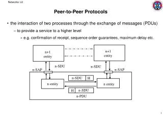
Service And Environment As an example, assume we want to implement a data transmission protocol that provides for the encoding of characters into tuples of 7 bits each, and for some rudimentary error detection scheme to protect the bytes against transmission errors, for instance by the addition of one parity bit to each 7-bit byte. This protocol then provides two services: encoding and error detection. We can separate these two services into two functional submodules, an encoder and a parity module, and invoke them sequentially.
Service And Environment At the other end of the line, there will be a decoder and a parity checker. For full-duplex transmission, we can conveniently combine the function of the encoder and decoder into one module, say P2, and similarly we can combine the parity adder and checker into a single module P1.
Service And Environment The channel (the dashed line) is wrapped in two layers. Each layer provides a different service and implements a separate protocol. The first layer implements the P1 protocol; the second layer implements the P2 protocol. The data format of the P2 protocol is a 7-bit byte. The data format of the P1 protocol is an 8-bit byte. The P2 protocol does not see and does not know about the eighth bit that is added to its bytes. The only thing it cares about is that the channel its 7-bit bytes travel on is more reliable than the raw channel at the lower level. The P1 protocol provides a virtual channel for the P2 protocol, but is transparent to the P2 protocol.
Service And Environment As shown in this figure, each layer can enclose the data to be transmitted in a new data envelope, consisting of a header and/or trailer, before passing it to the next layer. The original data format from the upper layers need not even be preserved by the lower layers.
Service And Environment The main concept of a layering technique:
Service And Environment The protocol functions on the N-th layer form a logical entity. In the model they are referred to as peer entities. By convention the horizontal boundary between two adjacent layers is called an interface, and the vertical boundary between two entities in different systems is called a peer protocol. Since the local implementation details of the layer interfaces can easily be hidden from the environment, only the peer protocols must be standardized among systems.
Service And Environment The interface between two adjacent layers is defined as a collection of service access pointsimplemented by the lower layer and available to the higher layer. The information to be exchanged is formatted incrementally by the various layers in data unitsor data envelopes. In sequence, the information is passed from the sender down from the highest layer used, to the physical layer, transmitted via the actual physical circuit from system to system, and interpreted step by step while being passed up the protocol hierarchy again to the highest layer used by the receiver.
Service And Environment We can define the first two elements of the five-part protocol specification • the service to be provided by the protocol, and • the assumptions made about its environment as formal specifications of the upper and lower interface of a given protocol layer. The service is provided to the upper layer protocols, or to the user at the top layer. The assumptions made are assumptions about the services provided by the lower layer protocols. At the lowest protocol layer these assumptions concern the bare service provided by the physical transmission medium, i.e., an optical fiber or a copper wire.
Vocabulary and Format The three main formatting methods are: • Bit oriented • Character oriented • Byte-count oriented These formats must underly all higher-level structures, for example, the structures that are used to encode the protocol message vocabulary.
Vocabulary and Format BIT ORIENTED: A bit-oriented protocol transmits data as a stream of bits. To allow a receiver to recognize where a message starts and ends in the bit stream, a small set of unique bit patterns, or flags, is used. Of course, these bit patterns can be part of the user data too, so something has to be done to ensure that they are always interpreted properly.
Vocabulary and Format If a framing flag, for instance, is defined as a series of six one bits enclosed in zeros, 01111110, series of six adjacent ones in the user data must be intercepted. This can be done by inserting an extra zero after every series of five ones in the user data.
Vocabulary and Format The receiver can now correctly detect the structure enforced by the flags in the bit stream by inspecting the first bit after every series of five ones: if it is a zero it must be deleted, else the pattern being scanned must be part of a true frame delimiter. This is bit stuffingtechnique. Once the basic low-level flag structure is in place, it can be used to support higher-level structures.
Vocabulary and Format CHARACTER ORIENTED: In a character-oriented protocol some minimal structure is enforced on the bit stream. If the number of bits per character is fixed to n bits (typically 7 or 8), all communication takes place in multiples of n bits. These data units are then used to encode both user data and control codes.
Vocabulary and Format Examples of control codes are the ASCII start of text STX and end of text ETX messages that can serve as delimiters and can be used to enclose the user data. Again, if raw data are transmitted care must be taken that the delimiters do not accidentally occur in the user data.
Vocabulary and Format Every control character, such as STX and ETX, is preceded by an extra code, the data link escape character DLE. If any control message, such as STX, ETX, or even DLE itself, happens to occur literally in the user data, it is preceded by an extra DLE character. The DLE code is interpreted by the receiver as a control code that turns off any special meaning of the first character that follows it. The receiver deletes the first DLE code that it sees in the character stream, and passes on the following character uninterpreted. Only if the special meaning of an STX or ETX code is not suppressed by a preceding DLE character is it interpreted as a delimiter. The technique is called character stuffing.
Vocabulary and Format BYTE-COUNT ORIENTED: In a known place after the STX control message, the sender includes the precise number of bytes (characters) that the message contains. An ETX message is now superfluous, and techniques such as bit stuffing or character stuffing are no longer needed. Most protocols in use today are of this type.
Vocabulary and Format HEADERS AND TRAILERS: So far we have silently assumed the absence of transmission errors. If a byte-count field is distorted, or a DLE character is lost, these techniques fail. Error detection schemes require transmission of redundant information, typically in the form of a checksum. If flow control techniques are added, for instance to detect loss or reordering of text frames, a sequence number field is appended.If more than one type of message is used we further have to include an indication of the type of message being transferred.
Vocabulary and Format All this overhead is most conveniently grouped into separate structures that encapsulate the user data: a mere STX control message thus expands into a headerstructure, and similarly the simple ETX grows into a composite message trailer. For obvious reasons, byte counts are typically placed in message headers and checksums are placed in the trailer. The message format may then be defined as an ordered set of three elements: format = { header, data, trailer }.
Vocabulary and Format The header and trailer again define ordered subsets of control fields, which may be defined as follows: header = { type, destination, sequence number, count }, trailer = { checksum, return address }.
Vocabulary and Format The type field can be used to identify the messages that make up the protocol vocabulary. Depending on the particular structure of the protocol vocabulary, this field can be refined still further.
Procedure Rules An important aspect of the protocol design problem is that the procedure rules are interpreted concurrently by a number of interacting processes. The effect of each new rule we add to the set is often much larger than can be foreseen. Many different interleavings in time of the interpretation of these rules by the various processes will be possible. Precisely because of this concurrency a protocol behavior is not always reproducible. To convince ourselves of the correctness of a design we need something better than informal reasoning.
Procedure Rules We must be able to express behavior unambiguously in a convenient formal notation. Transition tables, formal finite state machines, MSC or SDL diagrams, for instance, can be used for this purpose. There is no general methodology that can guarantee apriorithe design of an unambiguous set of procedure rules. There are, however, tools with which we can, even automatically, verify the logical consistency of the rules and the observance of the correctness requirements. And, of course, there is common sense and plain good engineering practice that can help us to keep the protocol rules manageable.