Download
1 / 45
730 likes | 1.17k Views
Bioreactor Design . Microbial Fuel Cell. Lecturer: Sara Madani Supervisor: Reza Gheshlaghi. How Much Energy Will We Need In The Future?. Oil will not appreciably run out for at least 100 years or more, demand for oil is expected to exceed.

E N D
Bioreactor Design Microbial Fuel Cell Lecturer: Sara Madani Supervisor: Reza Gheshlaghi
How Much Energy Will We Need In The Future? • Oil will not appreciably run out for at least 100 years or more, demand for oil is expected to exceed. • The costs of energy and how much energy we use will come to dominate our economy and our lifestyle. • The total annual energy consumption = 13.5 *1012 W (2006). • Global demand of 41 * 1012 W in 2050. • The release of stored carbon in fossil fuels is increasing the concentration of carbon dioxide in the atmosphere. (from 316 ppmv in 1959 to 377 ppmv in 2004). • By 2100, C 0 2 concentrations will reach from 540 to 970 ppmv. • If we obtain energy from these sources using conventional technologies, we will release additional CO2, exacerbate environmental damage, and global climate change. Microbial fuel cell Bruce E. Logan The Pennsylvania State UniversityPub John Wiley . Inc., Hoboken, New Jersey (2007).
Renewable Energy Resources Our greatest environmental challenge is to simultaneously solve energy production and CO2 releases. • Nuclear fission • Solar energy • Geothermal • Wind • Hydroelectricity • Biofuel Thus, our best solution for both energy and climate appears to be heavy investment in renewable energy resources, in terms of both research and development. Microbial fuel cell Bruce E. Logan The Pennsylvania State UniversityPub John Wiley . Inc., Hoboken, New Jersey (2007).
Energy Consumption In Iran Total ultimate energy consumption in Iran was 1033.32 MBOE in 2006. and increased at an average annual rate of 6% in 1996-2006. • [1 barrel of oil equivalent (boe)]. • Iran’s ultimate energy consumption pattern over the last decades is inefficient and contributes towards the excessive consumption of fossil fuels which produces several quantities of pollutants and green house gases. • Low price of energy and high subsidies. • represent an effective incentive for inefficient energy consumption pattern and accelerate energy consumption and environmental pollutions. Analysis of Ultimate Energy Consumption by Sector in Islamic Republic of Iran /B. FARAHMANDPOUR∗, I. NASSERI, H. HOURI JAFARI Energy Management Department/3rd IASME/WSEAS Int. Conf. on Energy & Environment, University of Cambridge, UK, February 23-25, 2008
Comparison Of Energy Consumption Total Energy consumption in iran(2007) Total energy consumption in USA(2003) http://www.eia.doe.gov/cabs/Iran/Background.html /Microbial fuel cell Bruce E. Logan The Pennsylvania State UniversityPub John Wiley . Inc., Hoboken, New Jersey (2007).
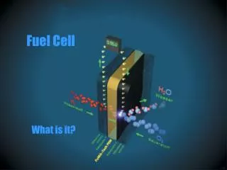
Microbial Fuel Cells (MFCs) – An Introduction • Microbial fuel cells (MFCs) have emerged in recent years as a promising yet challenging technology. • MFCs are the major type of bioelectrochemical systems (BESs) which convert biomass spontaneously into electricity through the metabolic activity of the microorganisms. • MFC is considered to be a promising sustainable technology to meet increasing energy needs, especially using wastewaters as substrates, which can generate electricity and accomplish wastewater treatment simultaneously • It may offset the operational costs of wastewater treatment. A review of the substrates used in microbial fuel cells (MFCs) for sustainable energy production Deepak Pant *, Gilbert Van Bogaert, Ludo Diels, KarolienVanbroekhoven
Microbial Fuel Cells (MFCs) Have Gained A Lot Of Attention In Recent Years The number of articles on MFCs. The data is based on the number of articles mentioning MFC in the citation database Scopus in September’ 2009 A review of the substrates used in microbial fuel cells (MFCs) for sustainable energy production Deepak Pant *, Gilbert Van Bogaert, Ludo Diels, KarolienVanbroekhoven
Chemistry of MFC: Anode Chemistry of MFC: Cathode MFC Components: • Oxidation –reduction reaction • Substrate : Acetate TEA: Oxygen • Substrate : Glucose TEA: Ferricyanide
MFC Components: • Anode: Anodic materials must be conductive, biocompatible, and chemically stable in the reactor solution. • Anode Material: Carbon Paper, Cloth, Carbon Rod, Foams, Reticulated Vitrified Carbon RVC ,Graphite Fiber, Graphite Rods, Felt, Plates, Graphite Granules, And Sheets, Woven Graphite. The highest specific surface areas and porosities Microbial fuel cell Bruce E. Logan The Pennsylvania State UniversityPub John Wiley . Inc., Hoboken, New Jersey (2007).
MFC Components: Cathode • Air cathods • Aqueous catholytes : Ferricyanide, Permanganate, iron Abiotic Biotic (biocathods)
MFC Components: • Cathode: The same materials that have been described for use as the anode have also been used as cathodes. • Catalysts • Electrode • Binder • Catholye • catalyst is usually (i.e., Pt for oxygen reduction) but not always needed (i.e., ferricyanide). • The chemical reaction that occurs at the cathode is difficult to engineer as the electrons, protons and oxygen must all meet at a catalyst in a tri-phase reaction (solid catalyst, air, and water).
MFC Components: • Membrane : primarily used as a method for keeping the anode and cathode liquids separate. • Cation or Anion Exchange Membranes, or any permeable material, can function as a solution barrier in an MFC if charge can be transferred. • Membrane material: Cation exchange membranes (CEM) CMI-7000, PEM Nafion 117,AEM ,Bipolar Memrane , Ultrafiltration(UF) Membranes.
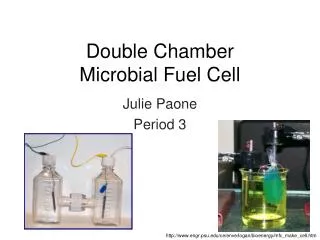
Double Chamber MFC • Two-chamber air-cathode cube type MFC • it useful to examine the effect of different membrane types under similar conditions. • High internal resistance • Low power density Microbial fuel cell Bruce E. Logan The Pennsylvania State UniversityPub John Wiley . Inc., Hoboken, New Jersey (2007).
Single Chamber Air-cathode Cube System • A useful and simple design for examination factors. • Substrate:Glucose • P=494± 21 (no CEM). • P=262±10 ( CEM). Microbial fuel cell Bruce E. Logan The Pennsylvania State UniversityPub John Wiley . Inc., Hoboken, New Jersey (2007). Energy Sustainability of the Water Infrastructure Bruce E. Logan Penn State University (2008)
Continuous- Single-ChamberDesigns Tubular MFC With Inner Cathode Compartment • SCAC MFC :a cathode tube concentric with eight graphite anodes in an acrylic tube casing. • This reactor was used to demonstrate electricity production with simultaneous wastewater treatment. [Liu et a/. (2004). Microbial fuel cells: novel biotechnology for energy generation KorneelRabaey and Willy Verstraete. TRENDS in Biotechnology Vol.23 No.6 June (2005).
Tubular Upflow Reactor Designs • Anode & Cathod:(RVC) • The flow was directed towards the CEM • Internal resistance =84 Ω (limited power production) • Anode :conductive graphite granules • Cathode:thick woven graphite mat • Catholyte:ferricyanide Microbial fuel cell Bruce E. Logan The Pennsylvania State UniversityPub John Wiley . Inc., Hoboken, New Jersey (2007).
Mechanisms Of Electron Transfer • Direct contact through outer-membrane proteins. • Diffusion of soluble electron shuttles. • Dlectron transport through solid components of the extracellular biofilm matrix. A kinetic perspective on extracellular electron transfer by anode-respiring bacteria /C´ esar I. Torres, Andrew Kato Marcus, Hyung-Sool Lee, PrathapParameswaran, Rosa Krajmalnik-Brown & Bruce E. Rittmann./FEMS Microbiol Rev 34 (2010) 3–17
Mechanisms Of Electron Transfer • Direct contact of anode-respiring bacteria cannot achieve high current densities due to the limited number of cells. • Slow diffusive flux of electron shuttles at commonly observed concentrations limits current generation and results in high potential losses. • Only electron transport through a solid conductive matrix can explain observations of high current densities and low anode potential losses. A kinetic perspective on extracellular electron transfer by anode-respiring bacteria /C´ esar I. Torres, Andrew Kato Marcus, Hyung-Sool Lee, PrathapParameswaran, Rosa Krajmalnik-Brown & Bruce E. Rittmann./FEMS Microbiol Rev 34 (2010) 3–17
Solid Conductive Matrix Mechanism • The solid conductive matrix is likely to act as a semi-conductor (10-6mS /cm<k<106mS/cm) rather than as a conductor. A kinetic perspective on extracellular electron transfer by anode-respiring bacteria /C´ esar I. Torres, Andrew Kato Marcus, Hyung-Sool Lee, PrathapParameswaran, Rosa Krajmalnik-Brown & Bruce E. Rittmann./FEMS Microbiol Rev 34 (2010) 3–17
BOTTLENECKS OF MICROBIAL FUEL CELLS • Anode compartment: potential losses decrease MFC voltage. • Transport of charge and ions in the electrolyte: the influence of turbulence. • Membrane resistance, selectivity and O2permeability. • The structure of the anode • The role of the cathode performance Microbial fuel cells: performances and perspectives /KorneelRabaey, GeertLissens and Willy Verstraete.(2005).
Polarization Curve In Fuel Cells • Activation overpotentials: major limiting factor in MFC Voltage losses due to bacterial metabolism • Ohmic losses :intarnal resistance • Concentration polarization: Microbial fuel cells: performances and perspectives /KorneelRabaey, GeertLissens and Willy Verstraete.(2005).
Activation Overpotential Activation losses are due to energy lost (as heat) : • Voltage losses due to bacterial metabolism : bacteria need sufficient energy only to pump one proton across a membrane. • Reducing a compound at the bacterial surface requires certain energy to activate the oxidation reaction. • Energy lost through the transfer of an electron from the cell terminal protein to the anode surface. ( the nanowire, mediator, or terminal cytochrome at the cell surface). • Oxidizing a compound at the anode surface. • Microbial fuel cells: performances and perspectives /KorneelRabaey, GeertLissens and Willy Verstraete(2005)/ Microbial fuel cell Bruce E. Logan The Pennsylvania State UniversityPub John Wiley . Inc., Hoboken, New Jersey (2007).
potential losses(Edonor-Eanode) • The intracellular potential : Edonor-EOM The EET potential loss : EOM-Einterface • The electrodeinterface reaction potentialloss : • Einterface-Eanode • Overall anode potential losses • Edonor-Eanode A kinetic perspective on extracellular electron transfer by anode-respiring bacteria /C´ esar I. Torres, Andrew Kato Marcus, Hyung-Sool Lee, PrathapParameswaran, Rosa Krajmalnik-Brown & Bruce E. Rittmann./FEMS Microbiol Rev 34 (2010) 3–17
Voltage losses due to bacterial metabolism • Schematic of processes involved in intracellular potential losses. • 1)Substrate utilization : • electrons are transferred from the electrondonor (Edonor) to intracellular reducing power (NADH). • 2) Extracellular electron production : • ARB have produced the reduced intracellular carrier (NADH), they initiate electron flow through the electron transport chain until the electrons reach membrane-bound cytochromes (ηOM), resulting in a potential loss. j: current density obtained by ARB jmax: the maximum current density of the ARB biofilm, S : the substrate concentration in the liquid Ks, app: the apparent half-saturation substrate concentration in a biofilm. R: ideal gas constant (8.3145 J mol^-1 K^-1) F:Faraday constant (96 485 C mol^-1 e-) T: temperature (K) EKA: the potential at which j = 1/2jmax (V) A kinetic perspective on extracellular electron transfer by anode-respiring bacteria /C´ esar I. Torres, Andrew Kato Marcus, Hyung-Sool Lee, PrathapParameswaran, Rosa Krajmalnik-Brown & Bruce E. Rittmann./FEMS Microbiol Rev 34 (2010) 3–17
Solid conductive matrix mechanism • (EOM-Einterface) • Depending on the characteristic of the solid conductive matrix, its conductivity could be modeled using various equations that describe conductors and semi-conductors (Seeger, 1997). • We can use Ohm’s Law: Kbio : the conductivity of the solid conductive matrix(Ω^-1 L^-1)` A kinetic perspective on extracellular electron transfer by anode-respiring bacteria /C´ esar I. Torres, Andrew Kato Marcus, Hyung-Sool Lee, PrathapParameswaran, Rosa Krajmalnik-Brown & Bruce E. Rittmann./FEMS Microbiol Rev 34 (2010) 3–17
Schematic of three EET mechanisms used • (a) direct electron transfer, • (b) electron shuttles, • (c) solid conductive mechanism. • 1)substrate utilization • 2) electron production • 3a) electron shuttle transport between ARB and the electrode • 3b) electron transport across a solid conductive matrix; • 4) interface electron transfer to the electrode. kinetic perspective on extracellular electron transfer by anode-respirAing bacteria /C´ esar I. Torres, Andrew Kato Marcus, Hyung-Sool Lee, PrathapParameswaran, Rosa Krajmalnik-Brown & Bruce E. Rittmann./FEMS Microbiol Rev 34 (2010) 3–17
Several Solutions To Reduce Activation Loss • Increasing the operation temperature • Decreasing the activation losses at the electrode surface Addition of a catalyst to the electrode Increasing the roughness and specific surface of the electrode • Decreasing the activation losses at the bacteria A redox mediator can be added to the anode compartment • Microbial fuel cells: performances and perspectives /KorneelRabaey, GeertLissens and Willy Verstraete(2005)/ Microbial fuel cell Bruce E. Logan The Pennsylvania State UniversityPub John Wiley . Inc., Hoboken, New Jersey (2007).
OhmicOverpotential • Electrical resistances of the electrodes • Electrolyte • Membrane • They are important at higher current levels. • A resistance of only 15 Ω causes a potential loss of 150 mV at a current of 10 mA, a loss not to be neglected. • Reducing electrode spacing. • Choosing membranes or electrode coatings with low resistances. • Ensuring good contacts between the circuit and electrodes Increasing solution conductivity and buffering capacity. • Microbial fuel cells: performances and perspectives /KorneelRabaey, GeertLissens and Willy Verstraete(2005)/ Microbial fuel cell Bruce E. Logan The Pennsylvania State UniversityPub John Wiley . Inc., Hoboken, New Jersey (2007).
Concentration Polarization (Mass Transfer Losses) • This is a problem only occurring at higher current densities • When the flux of reactants to the electrode or the flux of products from the electrode are insufficient and therefore limit the rate of reaction. • Thick non-conductive biofilm • Substrate flux • Proton flux from the anode • Microbial fuel cells: performances and perspectives /KorneelRabaey, GeertLissens and Willy Verstraete(2005)/ Microbial fuel cell Bruce E. Logan The Pennsylvania State UniversityPub John Wiley . Inc., Hoboken, New Jersey (2007).
? ? ? But wait…There’s More! ?
Thank you for your time, and interest in microbial fuel cells!
Direct Contact Mechanism • We calculate the maximum current density achievable by this monolayer biofilm using a simple biofilm model. jmax is a function of the active biofilm thickness according to the following equation
Soluble electron shuttle mechanism • The use of electron shuttles allows ARB to be located away from the anode surface and to accumulate more than a monolayer of bacteria. • Although shuttles allow more ARB to be active per anode surface area, the distance between ARB and the anode becomes a limiting factor due to diffusion limitations of the electron shuttles (Picioreanu et al., 2007).
Soluble electron shuttle mechanism • transport of soluble electron shuttles is mainly carried out by diffusion through Fick’s law, shown here modified to reflect current density calculations: Dshuttle: the diffusion coefficient of the electron shuttle (m2 /s1) Δz : the transport distance (m), Δcshuttle : the concentration gradient of either oxidized or reduced shuttle (mol/m3), nF :converts from moles to coulombs.
Soluble electron shuttle mechanism • The total current density obtained by ARB using electron shuttles can be limited by the diffusion of electron shuttles according to Eqn. (5). • Diffusion coefficients of organic molecules are relatively small, indicating that diffusion is an inherently slow process. • if we can assume electron shuttles is similar to other organic molecules, such as glucose, then Dshuttle ≈Dglucose=6.7 *10^-10 (m2 /s)
Soluble electron shuttle mechanism • ΔCshuttle is limited by the total concentration of electron • shuttles present in the ARB biofilm. Dshuttle=6.7 *10^-10 (m2 /s). • ΔCshuttle=1µM=1*10^-3( mol/m3), and n = 2 for the electron shuttle reaction (Kubota & Gorton, 1999; von Canstein et al., 2008), • the flux of an electron shuttle across 1 mm of biofilm • (Δz=1mm) is only 0.13 (A/m2). • This calculated value is 100 times smaller than observed current densities.
Soluble electron shuttle mechanism • The potential loss for an electron-shuttle reaction • can be calculated by the Nernst equation: • The value for E0 is also an important parameter to characterize the potential loss of electron shuttles, as it at which the current density approaches zero (j0) by Butler–Volmer kinetics
Soluble electron shuttle mechanism • Loss of electron shuttles in the effluent of the MXC poses Another challenge to its use by ARB. • A few studies showed a decrease in current density when the medium was replaced in batch experiments using ARB that produce electron shuttles (Bond & Lovley, 2005; Marsili et al.,2008a). • This effect could be stronger in a continuous system, where the steady loss of electron shuttles in the effluent liquid decreases their concentration in the biofilm significantly. • Marsili et al. (2008a) have proposed that electron shuttles can be at higher concentrations inside the biofilm by binding to the electrode surface and biomass. • Binding cannot increase the flux of electrons throughdiffusion, because the attached shuttles cannot diffuse.
Solid conductive matrix mechanism • It is also unknown whether nanowires are themselves conductive or whether they serve as a surface for conductive proteins/polymers to attach. • Recent studies have shown that ARB known to produce a solid conductive matrix can produce high current densities.
The Butler – Volmer equation describes the finalpotential loss for all EET mechanisms • j0 : the exchange current density (A/m2) • α : the electron-transfercoefficient or the symmetry coefficient for the anodic or the cathodic reaction • Eanode :the anode potential (V) • E0interface :the standard potential (V) of the reaction occurring at the anode interface. • this reaction can occur between a protein and the anode or by a compound (such as an electron shuttle) and the anode. A kinetic perspective on extracellular electron transfer by anode-respiring bacteria /C´ esar I. Torres, Andrew Kato Marcus, Hyung-Sool Lee, PrathapParameswaran, Rosa Krajmalnik-Brown & Bruce E. Rittmann./FEMS Microbiol Rev 34 (2010) 3–17
Summary of kinetic analysis on the three EET mechanisms known to be used by ARB • A kinetic perspective on extracellular electron transfer by anode-respiring bacteria /C´ esar I. Torres, Andrew Kato Marcus, Hyung-Sool Lee, PrathapParameswaran, Rosa Krajmalnik-Brown & Bruce E. Rittmann./FEMS Microbiol Rev 34 (2010) 3–17
units • ppmv= ppm by volume (i.e., volume of gaseous pollutant per 106 volumes of ambient air). • The SI unit of conductivity is siemens per meter (S/m). • 1siemens = reciprocal of one ohm