Lecture 5 Capacitance Ch. 25
Lecture 5 Capacitance Ch. 25. Cartoon - Capacitance definition and examples. Opening Demo - Discharge a capacitor Warm-up problem Physlet Topics Capacitance Parallel Plate Capacitor Dielectrics and induced dipoles Coaxial cable, Concentric spheres, Isolated sphere

Lecture 5 Capacitance Ch. 25
E N D
Presentation Transcript
Lecture 5 Capacitance Ch. 25 • Cartoon - Capacitance definition and examples. • Opening Demo - Discharge a capacitor • Warm-up problem • Physlet • Topics • Capacitance • Parallel Plate Capacitor • Dielectrics and induced dipoles • Coaxial cable, Concentric spheres, Isolated sphere • Two side by side spheres • Energy density • Graphical integration • Combination of capacitance • Demos • Super VDG • Electrometer • Voltmeter • Circular parallel plate capacitor • Cylindrical capacitor • Concentric spherical capacitor • Dielectric Slab sliding into demo • Show how to calibrate electroscope
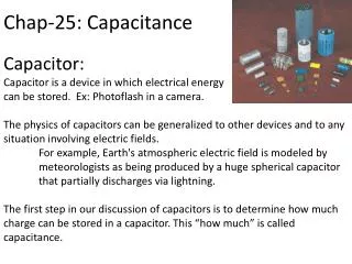
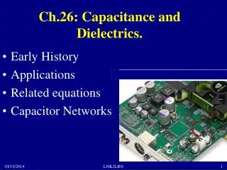
Capacitance • Definition of capacitance • A capacitor is a useful device in electrical circuits that allows us to store charge and electrical energy in a controllable way. The simplest to understand consists of two parallel conducting plates of area A separated by a narrow air gap d. If charge +Q is placed on one plate, and -Q on the other, the potential difference between them is V, and then the capacitance is defined as . • The SI unit is , which is called the Farad, named after the famous and creative scientist Michael Faraday from the early 1800’s. • Applications • Radio tuner circuit uses variable capacitor • Blocks DC voltages in ac circuits • Act as switches in computer circuits • Triggers the flash bulb in a camera • Converts AC to DC in a filter circuit
Electric Field of Parallel Plate Capacitor Gaussian surface + q + + + + + + + + + + + E d A Area of plate =A - - - - - - - - - - - - q Integrate from - charge to + charge so that Coulomb/Volt = Farad
Show Demo Model, calculate its capacitance, and show how to charge it up with a battery. Circular parallel plate capacitor r = 10 cm = 0.1m A = r2 = (.1m)2 A = .03 m 2 d = 1 mm = .001 m r r d p = pico = 10-12
Demo Continued • Demonstrate • 1. As d increases, voltage increases. • 2. As d increases, capacitance decreases. • 3. As d increases, E0 and q are constant.
Dielectrics • A dielectric is any material that is not a conductor, but polarizes well. Even though they don’t conduct they are electrically active • Examples. Stressed plastic or piezo-electric crystal will produce a spark. • When you put a dielectric in a uniform electric field (like in between the plates of a capacitor), a dipole moment is induced on the molecules throughout the volume. This produces a volume polarization that is just the sum of the effects of all the dipole moments. If we put it in between the plates of a capacitor, the surface charge densities due to the dipoles act to reduce the electric field in the capacitor.
Induced dipoles Permanent dipoles _ ++ _ E0 = the applied field E’ = the field due to induced dipoles E = E0 - E’
Dielectrics • The amount that the field is reduced defines the dielectric constant from the formula , where E is the new field and E0 is the old field without he dielectric. • Since the electric field is reduced and hence the voltage difference is reduced (since ), the capacitance is increased. • where is typically between 2 – 6 with water equal to 80. • Show demo dielectric slab sliding in between plates. Watch how capacitance and voltage change. Also show aluminum slab.
Find the capacitance of a ordinary piece of coaxial cable (TV cable) Integrate from b to a or - to + b a air Va is higher than Vb
capacitance of a coaxial cable cont. a = 0.5 mm b = 2.0 mm 2 Now if a=0.5mm and b=2.0mm, then And if k = 2, then For = 2 0 (for air)
Model of coaxial cable for calculation of capacitance Outer metal braid Signal wire - to +
Capacitance of two concentric spherical shells -q Integration path dr as +q b a E for an isolated sphere Let b get very large. Then
Q R Spherical capacitor or sphere Recall our favorite example for E and V is spherical symmetry The potential of a charged sphere is with V = 0 at r = . The capacitance is Where is the other plate (conducting shell)? It’s at infinity where it belongs, since that’s where the electric lines of flux terminate. k = 1010 and R in meters we have Earth: C = (6x108 cm)pF = 600 F Marble: 1 pF Basketball: 15 pF You: 30 pF Demo: Show how you measured capacitance of electroscope
a a Capacitance of one charged conducting sphere of radius a relative to another oppositely charged sphere of radius a d d d =20 cm a =10 cm m =0.5 C=10-10(.1) (1+.5 +.25 +.125….) C=10-10(.1)(1/(1-m)) C= 0.2 x 10⁻¹⁰ F C= 0.02 nF =20 pF C = 40a (1+m+m2+m3+m4+…..) m= a/d d >>a If d gets very large, then C= 10 pF
using Also Electric Potential Energy of Capacitor • As we begin charging a capacitor, there is initially no potential difference between the plates. As we remove charge from one plate and put it on the other, there is almost no energy cost. As it charges up, this changes. At some point during the charging, we have a charge q on the positive plate. The potential difference between the plates is As we transfer an amount dq of positive charge from the negative plate to the positive one, its potential energy increases by an amount dU. The total potential energy increase is
where V V = q/c q/c = Area under the triangle q dq Q Area under the triangle is the value of the integral Graphical interpretation of integration Area of the triangle is also =
and volume occupied by E Where is the energy stored in a capacitor? Find energy density for parallel plate capacitor. When we charge a capacitor we are creating an electric field. We can think of the work done as the energy needed to create that electric field. For the parallel plate capacitor the field is constant throughout, so we can evaluate it in terms of electric field E easily. Use U = (1/2)QV We are now including dielectric effects: Solve for Q = AE, V = ES and substitute in Electrostatic energy density general result for all geometries. To get total energy you need to integrate over volume.
How much energy is stored in the Earth’s atmospheric electric field?(Order of magnitude estimate) atmosphere 20 km h Earth R R = 6x10⁶ m World consumes about 1018 J/day. This is 1/2000 of the solar flux. This energy is renewed daily by the sun. Is this a lot? The total solar influx is 200 Watts/m2 Only an infinitesimal fraction gets converted to electricity.
Parallel Combination of Capacitors Typical electric circuits have several capacitors in them. How do they combine for simple arrangements? Let us consider two in parallel. Q2 Q1 We wish to find one equivalent capacitor to replace C1 and C2. Let’s call it C. The important thing to note is that the voltage across each is the same and equivalent to V. Also note what is the total charge stored by the capacitors? Q.
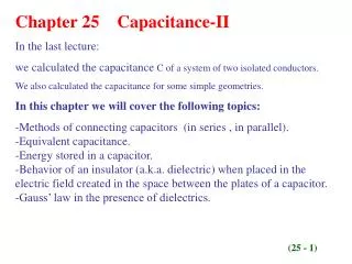
So Therefore, Series Combination of Capacitors Q Q V1 V2 What is the equivalent capacitor C? Voltage across each capacitor does not have to be the same. The charges on each plate have to be equal and opposite in sign by charge conservation. The total voltage across each pair is:
Sample problem C1 = 10 F C2 = 5.0 F C3 = 4.0 F a) Find the equivalent capacitance of the entire combination. C1 and C2 are in series. C12 and C3 are in parallel.
Sample problem (continued) C1 = 10 F C2 = 5.0 F C3 = 4.0 F b) If V = 100 volts, what is the charge Q3 on C3? C = Q/V c) What is the total energy stored in the circuit?