Download
1 / 13
130 likes | 261 Views
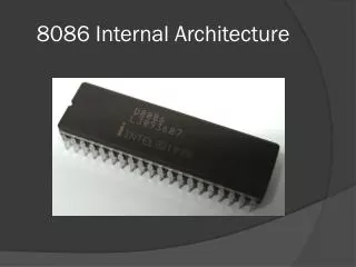
8086 Internal Architecture. 8086 Architecture. 8086 Microprocessor is divided into two independent functional parts. The Execution Unit (EU). Bus Interface Unit (BIU). This division into two units speeds up processing. 8086 Architecture. The Execution Unit.

E N D
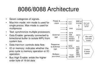
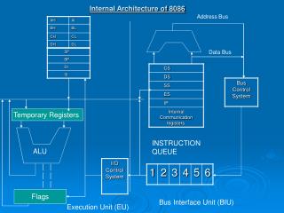
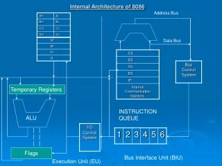
8086 Architecture • 8086 Microprocessor is divided into two independent functional parts. • The Execution Unit (EU). • Bus Interface Unit (BIU). • This division into two units speeds up processing.
The Execution Unit • EU contains control circuitry which directs internal operations. • A decoder in the EU translates instructions fetched from memory into a series of actions which EU carries out. • EU consists of GPR’s and other Pointer and Index registers. • EU consists of 16 bit ALU which carries out addition, subtraction, AND, OR, XOR, increment, decrement, complement, or shift binary numbers.
Bus Interface Unit • The BIU sends out addresses, fetches instructions from memory, reads data from ports and memory, and writes data to ports and memory. • In other words BIU handles all transfer of data and addresses on the buses for the execution unit.
Instruction QUEUE • While an EU is decoding an instruction or executing an instruction which does not require use of the buses, the BIU fetches upto 6 instructions bytes for the following instruction. • The BIU stores these prefetched bytes in a FIFO register set called a queue. • When EU is ready for its next instruction, it simply reads the queue in the BIU. • This is much faster than sending out the address to the memory and waiting for the memory to send back the next instruction byte.
Machine Cycle • Each time CPU executes an instruction it takes some steps, called machine cycle. • A machine cycle can be broken down into smaller cycles such as instruction cycle and execution cycle. • Fetching: Before the CPU can execute an instruction, the control unit must retrieve (or fetch) a command or data from the computer’s memory. • Decoding: Before a command can be executed, the control unit must break down (or decode) the command into instructions. • Executing: Part of the execution cycle. When the command is executed, the CPU carries out the instructions in order by converting them into microcode. • Storing: The CPU maybe required to store the results of an instruction in memory.
Pipelining • Fetching the next instruction while the current instruction executes is called pipelining. • The control unit begins a new machine cycle, that is it begins executing a new instruction before the current cycle is completed. • Executions are performed in stages, when the first instruction completes the fetching stage, it moves to the decode stage, and a new instruction is fetched. • Using this technology, new microprocessors can execute up to six instructions simultaneously
Stack Addressing • The 8086 let you set aside an entire 64Kb segment as a stack. • The upper 16bits of the starting address for this segment are kept in the stack segment register. • The stack pointer register holds the offset (16 bit). • The memory location where a word was most recently stored is called the top pf stack.
Stack Addressing • The physical address for a stack read or a stack write is produced by adding the contents of the stack pointer register to the stack segment register. • Example: SS = 5000H * 10H = 50000H SP = FFE0H SS + SP = 50000H + FFE0H = 5FFE0H
Immediate Addressing Mode • Suppose that in a program you need to put the number 437BH in the CX register. • The MOV CX, 437BH instruction can be used to do this. • When it executes this instruction will put the immediate hexadecimal number 437BH in the 16-Bit CX register. • This is referred to as immediate addressing mode.
Register Addressing Mode • Register addressing mode means that the register is the source of an operand for an instruction. • Example: The instruction MOV CX,AX. • The destination location is specified before the comma and the source is specified after the comma. • Note that the content of AX are just copied to CX, not moved.
Direct Addressing Mode • For the simplest memory addressing mode, the effective address is just a 16-Bit number written directly in the instruction. • Example: MOV BL, [437AH]. • The square brackets around the 437AH are shorthand for the content of the memory location. • When executed the content of that memory location will be copied in the BL register. • The BIU calculates the 20-Bit physical address by adding the effective address 437AH to the segment base address. • This is called direct addressing mode.

![8086 [2]](https://cdn1.slideserve.com/2457127/8086-2-dt.jpg)