Experimental Program in ATF
Experimental Program in ATF. Brief Introduction of present ATF/ATF2 Low Emittance Study Fast Ion Study N. Terunuma, KEK LER11, Heraklion , Crete, Greece, 2011/Oct/4. An important technical challenge of ILC is the collision of extremely small beams of a few nanometers in vertical size.

Experimental Program in ATF
E N D
Presentation Transcript
Experimental Program in ATF Brief Introduction of present ATF/ATF2 Low Emittance Study Fast Ion Study N. Terunuma, KEK LER11, Heraklion, Crete, Greece, 2011/Oct/4
An important technical challenge of ILC is the collision of extremely small beams of a few nanometers in vertical size. • ATF/ATF2 will address the development of the techniques for following issues: • Achieve the small vertical emittance • ATF-DR 4 pm 2 pm (ILC) or 1 pm • Demonstrate the ILC final focus optics • achieve the 37 nm vertical beam size at the IP • Stabilize the the beam position in a few nanometer level at the IP. • The ATF international collaboration is strongly promoting these activities. Challenging goals for ATF/ATF2
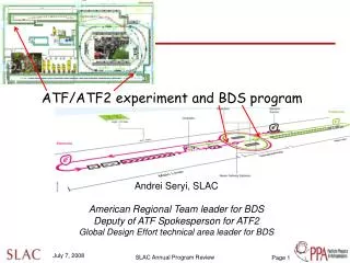
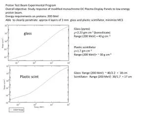
KEK Accelerator Test Facility (ATF) Energy: 1.3 GeV, Repetition: 1.56 Hz Intensity: 1x10¹⁰ e-/bunch (max. 2x10¹⁰), 1~20 bunches/pulse Emittance: Design, 1 nm(H)/ 10 pm(V), Achieved 4 pm(V) ATF2 beam line (ILC Final focus test system) Previous EXT line (~Jun.2008) Damping Ring ~140 m Photo-cathode RF gun (Multi-bunch electron source) S-band Linac
Damping Ring ey~10pm Focal Point sy~37nm Extraction beamline Final Focus (FF) System ATF2 Overview Damping Ring Use a low emittance beam extracted from DR ~10 pm 37 nm vertical beam size
Low emittance tuning in ATF Damping RingReview off Old Experiences + Plans 2011.10. Kiyoshi Kubo (KEK)
History of Low Emittance in ATF DR • There were great efforts to achieve low vertical emittance since DR commissioning. • From the end of 2000 to 2002, we observed the lowest vertical emittance in DR about 10 pm. • After improvement of hardware, with software and simulation works, we constantly achieved lower than 5 pm at low intensity (N 0), and lower than 8 pm at high intensity (N~1E10)., which was lower than “designed” emittance. (2003) • Since then, basically no farther improvement till 2008. • We have not really pursued lower emittance. • Emiitance became larger. • Re-start low emittance studies from 2009 (or late 2008) • Emittance recovered • For further improvement • BPM electronics replaced. (finished in 2010) • Re- alignment (in this summer) K. Kubo(KEK)
Vertical emittance measured by Laser Wire (April 16, 2003) by Y.Honda Laser wire monitor is still the most accurate emittance monitor in ATF DR. But the measurement is time consuming. We use X-ray synchrotron radiation profile monitor as a real time monitor. K. Kubo(KEK)
DR Emittance Summary (single bunch) in EXT in EXT 2009 spring I=5-6x10⁹ 2009 autum I=4-5x10⁹ Measured vertical emittance (2009 Dec) XSR=8.56±0.46 pm, IF=8.43±1.79 pm, LW00 =3.50±1.78 pm, LW01=2.00±1.61pm under the poor laser intensity
= Toward the 2(or1) pm emittance =Simulation - correction(1) Three consecutive corrections: Simulate actual procedure Monitor: BPM (total 96) Corrector: Steering magnets (47 horizontal and 51 vertical) Skew Qauds (trim coils of sextupole magnets, total 72) • COD correction • Vertical COD-dispersion correction • Coupling correction K. Kubo(KEK)
= Toward the 2(or1) pm emittance = Old simulation of ATF DR emittance tuning ERRORS: (tried to reproduce actual condition, not confirmed) • Misalignment of magnets: as measured + random 30 micron offset + random 0.3 mrad. rotation • BPM error : offset 300 micron wrt nearest magnet, rotation 0.02 rad. measured misalignment K. Kubo(KEK)
Simulation - correction(2) (a) COD correction: using steering magnets, minimize and , :x(y): horizontal (vertical) BPM reading. (b) V-COD-dispersion correction: using steering magnets, minimize y: measured vertical dispersion. r : weight factor = 0.05 (c) Coupling correction: using skew quads, minimize x(y): horizontal (vertical) position change at BPM due to excitation of a horizontal steering magnet. Two horizontal steering magnets were used (Nsteer=2). About (n+1/2)p phase advance between the two. K. Kubo(KEK)
Emmitace, dispersion and coupling of each stage COD corrected e_y e_y C_xy Rms of vertical dispersion Dispersion corrected e_y e_y Rms of vertical dispersion C_xy K. Kubo(KEK)
Simulated vertical emittance Distribution from 500 random seeds COD+Dispersion+coupling Number of entries COD+Dispersion COD Original goal ey (pm) K. Kubo(KEK)
For lower emittance BPM offset error should be small (~100 mm) K. Kubo(KEK)
Magnet alignments (< 30mm) are important,(only) if BPM offset error is smalland for very low emittance K. Kubo(KEK)
Quad strength error should be small (<0.5%) Emittance, 90% random seeds are lower than that. (A few seeds give extremely large emittances which make plots of average useless.) K. Kubo(KEK)
Low emittance study SUMMARY Simulation: • BPM offset error should be (w.r.t. nearest magnet) small. • Beam based alignment measurement using good BPM system will make it possible. • Then, εy ~ 2 pm will be achieved. (if offset error < 0.1 mm) • Magnet re-alignment, RMS < 30 μm. • Then, εy ~ 1 pm will be achieved. • Realistic alignment model? • Quad strength error should be 0.5% or smaller • It may have been achieved already, but not confirmed. • Beam based optics measurement (Orbit Response Matrix) with good BPM system make it possible. What we need: • Good BPM system, which we have now. TBT analysis will be planed. • Good alignment. • Good software tools, etc. • Make measurements and analysis faster. • New correction methods? • Good emittance monitor. K. Kubo(KEK)
DR BPM Upgrade for 2 pm emittance • The original read-out system designed for the single path position measurement has a 10 mm resolution. • Upgraded BPM readout system: • FNAL-KEK collaboration • Broadband turn-by-turn mode (< 10 µm resolution) • Injection 1,000 turns • Extraction 64 turns • Narrowband mode with high resolution (~ 100 nm range) • 160 ms, 500,000 turns after injection • Installed in 2010 for all DR BPMs (96) Downmix box at the beamline BPM digitizer station
The most accurate emittance monitor in ATF DR. • 14.7µm laser wire for X scan • 5.7µm for Y scan • But the measurement is • time consuming. • (scan: 15 min for X, 6 min for Y) Laser Wire with Optical Cavity (DR) Multi-bunch separated measurement 300mW 532nm Solid-state Laser fed into optical cavity
X-ray SR Monitor (XSR) • Real-time monitor for emittance tuning in DR • X-Ray Telescope using Zone Plate at 3.2KeV • magnification : 20 • Non destructive measurement • High resolution (< 1mm) • 2D direct imaging of the electron beam • Exposure time (1 ms ~ 20 ms) image of 1ms exposure sx = 48.2 ± 0.5 [mm] sy = 6.4 ± 0.1 [mm] Zone plate SR X-ray beam line
Alignment: present situationDisplacement was measured after the 3.11 earthquake (Enlarged image) • after earthquake • Rough alignment in May • 1.5 mm wider(N-S) than the original design. When?? • New design was defined as wider but same circumference.
Alignment work should be continued: DR After earthquake, aligned in June, aligned in summer Horizontal Longitudinal all +2.0 mm - 2.0 mm +2.0 mm - 2.0 mm B Q Sx
Recovery of beam in DR (x1010 e/bunch)A stored beam was delivered to the dump of ATF2.No critical damage on the accelerator was found. 3 trains 3 trains 1.0x10¹⁰ XSR ready FONT Inspection of the radiation safety V-emittance (XSR) ~30pm Freq. Adjust 0.5x10¹⁰ Compton 2-mirror FFTB mover HAPS Cavity BPMs 6/3 6/17 6/1 6/8 6/10 6/13 6/24 6/30 DR rough alignment for checkout was continued in daytime.
Devices for FII study One Path Superposition of multi-turn One Path & multi-turn One Path Superposition of multi-turn
2004 Fast Ion Study at ATF Clear FII was measured in 2004. Most of the machine time was assigned for the study of the low emittance multi-bunch beam. After the ITRP’s cold LC selection, The target of R&D was shifted to the development of the ATF2 (ILC final focus) instruments. Several years later, the needs for low emittance were raised again but not enough time for tuning a beam and instruments. Example: multi-bunch beam size, 2009may19 Bunch Number 2009 0.4x10¹⁰/bunch 0.3x10¹⁰/bunch 0.1x10¹⁰/bunch Need clear signals! ~10 pm Lower emittance < 10 pm Good base vacuum pressure High intensity Laser Wire Monitor Bunch Number
FII study on 2007/3/13-14(2) 5mA/20bunches 10mA/20bunches 20mA/20bunches 70 pm 20 pm 0 We measured emittance of each bunch in a 20-bunch beam in the DR with a laser-wire monitor. No clear emittance blow-up along a train was observed up to 20mA/train. One of the reason may be the bigger vertical emittance compared with the data taken in 2004.
We need followings for this study… • Low emittance beam < 10 pm • Now, the 2 pm emittance study is started. • Situation for the FII study becomes better and better! • Difficulties are in the coexistence with other R&D programs… • Stable multi-bunch beam • Not enough tuning time for multi-bunch beam because of too much single-bunch programs • Good multi-bunch emittance monitor • Increase the LW signal is required. Under working. • We will try to resume the study under above boundary. Fast Ion Study at ATF
The KEK-ATF has challenging goals to develop the key technology for ILC. One of them is the achievement of 2 (or 1) pm vertical emittance. This study has been started. We are continuing the alignment work to recover the machine from the earthquake and also to realize the 2 pm low emittance beam. The fast ion study will be resumed too. Summary