Drift Chambers and Pattern recognisation
Drift Chambers and Pattern recognisation. Fabrizio Cei Pattern recognition ideas INFN & Pisa University Hajime Nishiguchi Kapton foils for DC cathode University of Tokyo Johny Egger DC status and tests PSI. DC Status and Tests. Hood and inner cathodes Print foils p M1 test


Drift Chambers and Pattern recognisation
E N D
Presentation Transcript
Drift Chambers and Pattern recognisation • Fabrizio Cei Pattern recognition ideas INFN & Pisa University • Hajime Nishiguchi Kapton foils for DC cathode University of Tokyo • Johny Egger DC status and tests PSI
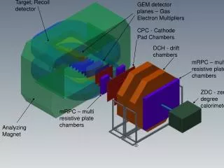
DC Status and Tests • Hood and inner cathodes • Print foils • pM1 test • Drift time measurement • Cathode read out • Next future
Cathode hood Delivery and first tests: second halfof July
Inner cathodes • measurement of deformation with applied forces • simulate forces (level arm) with wires through the gas holes • eventually stabilize free edges with tiny foam support(rohacell)
Print foils Good results of pM1 tests hood-foil tests with mounting tool Inner cathode foil mounting test possible foil pattern deformations Final design of the foil pattern Ordering if all requests are satisfied by the manufactory
H. Nishiguchi Kapton foils for DC cathodes Requirements Low-Mass: reduce resolution deterioration due to multiple scattering Kapton film 12.5 µm thick; Aluminum deposition 50 nm thick (NOT copper !! ) Accuracy: precise position reconstruction with vernier pad method requires manufacture accuracy ~ ±20 µm and deposition by “Etching”. Situation Sample foils with3 Japanese companies suffered frommany problems, buta sample foil which satisfies all requests (except cost) was built. Contacts with european factories under way from PSI group.
pM1 test with the 4 test chambers Anode 1, 2 plan 0 to 4 digital Scope 8 channels 500 MHz 500 points, 8 bits Cathodes of anode 2 plan 2,3 FLASH ADC 8 channels 100 MHz 500 points, 8 bits 24 Cathodes Anode 1,(2,3) LRS ADC 24 double channels Anode 3 plan 0 to 4 AD811 Read out
Parallel beam + tilted chambers Not staggered
DC tilted by a1 No Field P= 158 & 258 MeV/c 1.00 & .60 Tesla P= 158 & 258 MeV/c Dparallel < 1 % DC tilted by a2 s = .21 ns
Behavior of amplifiers in the 1 Tesla magnetic field • no measurable difference on induced test pulses • time definition : Dt = .12 ns ( s = .8 ns) • pulse integral : DI < .04 % (s = .16 % ) • -no measurable effect in the magnetic field even with magnetic SMD capacitors and resistances ( contacts) • approximate the field distortion with the new „non magnetic“ SMD elements, cables, connectors
Drift time Subtract y = b1 + b2*(sin[w*(t-t0)]): fit of the 225 first points pM1 run : w = 2p* 50 MHz Look for the first n=4,5 adjacent points above threshold Linear fit of first n signal points and n last background points (=0) threshold
(Fit-measured time) against drifttime Drift time t3 against t0 Sqrt( S(Fit-measured time)2 ) = > 2.0 ns2.8 ns(~.1 mm) 1.0 ns < s(Fit-measured time) < 2.1 ns Difference between 2 colors in t1 shows misalignment of anode w2p1 of ~.1 mm
u1-u2 u1+u2 u1 u2 d1d2 d1-d2 d1+d2 Cathode readout Anode has a shielding effect of a few percents Cathode u1 = n1*Anode * (1+c2 * sin[c3*x] + e * c2*sin2 [c3*x]) Cathode u2 = n2 *Anode * (1-c2 * sin[c3*x] - e * c2*sin2 [c3*x]) Cathode d1 = n3 *Anode * (1+c2 * cos[c3*x] + e * c2*cos2 [c3*x]) Cathode d2 = n4 *Anode * (1-c2 * cos[c3*x] - e * c2*cos2 [c3*x]) e value for traces on 1 side of the anode is the opposite of the value for traces on the other side
e and the cathode normalization factors ni are correlated in the calibration procedure Calibration procedure not yet optimal : distributions are not flat 0.34 mm < s(Fit-measured value) < .60 mm 0.11 mm < s(Fit-measured value) < .35 mm June 27 July 8
Cross talks a) to next plane < 1% b) To adjacent anode: 1) small on integrals 2) important for timimg c) to near cathode of adjacent anode: Important Corrections to b) and c) well defined by measurement of events without signal on the adjacent anode „Domino „ read out on all channels is important 1000 points, 500 MHz, 10 bits is ideal
Present and near future plane • Analysis of pM1 run(rich sample of data) • Magnetic field • Anode shielding, cross talk • Exotic events • Tests • Foils • Amplifiers and prints • High rates • Ordering • Foils • Frames and prints • Amplifiers and cables • Construction • Test with first elements(maybe within this year)
Positron Tracker 2002 2003 2004 2005 Medium Prototype Charge division & Cosmics Full Prototype FP FP Full Detector (18 DC) Design Manufactoring Assembly Test Milestone
Fabrizio Ideas for pattern recognition Pattern recognition problem in MEG: DC integration time~ 1 ms Positron rate on drift chambers~ 5 MHz Some superimposed tracks in each DC readout. Two turns (arather frequentcase)
Assumptions • Chambers are formed by two independent sensitive elements; • From each of them a three-dimensional information of the crossing point(“hit”) can be extracted DC signals were already analysed up to this level • Wiresandsignal formationnot simulated.
Strategy outline • Define a segment of track as two pairs of hits (ora pair and an isolated hit)withintwo adjacent chambers(one wedge); • Perform afastandreliable estimation of the positron momentum associated to any segment; • Look at any couple of segments which havethe same pair of hits(orthe same isolated hit)as end (one segment) and beginning (the other); • Select the couples of segments having compatible momentum components and total momentum; • Within this sample, join the couples of segments which satisfy the geometrical requirements for a good track; • Save all “tracks” formed by a minimum number of segments (4 or 5); • Absolute timing informationnot used (by now).
Not enough time for details; only Fast momentum estimation Technique: principal component analysis in quadratic approximation: Minimize: to determine ai, bij. hi = one of the three spatial coordinates of one hit. Sum overthe hits (3 or 4) in one wedge associated to a segment. Training by MC events: sample of 5 x 10⁵ Michel positron tracks, corresponding to ~ (1 3) x 104 tracksin each wedge.
Tracks with 4 segments Momentum reconstruction in one segment minus true value N.B. This is NOT a momentum reconstruction. py px Black: true Red: estimated pz p pz MeV Total momentum
Linking segments • Any chamber (except #1 and • #17) is a part of two“wedges” • we can link two segments in • adjacent wedges requiring that • they have one common point. • Further selections: • compatibility of momentum vectors in adjacent segments; • compatibility of new segment with extrapolated track. Segments with the same starting point.
Algorithm performances Michel positronsin the solid angle covered by the spectrometer or isotropically over the whole detector; no significant differences; positron momentum> 30 MeV; # of correctly reconstructed tracks Efficiency = ——————————————— # of generated tracks
A “by-product”: momentum estimation Not a momentum reconstruction, but a reasonable starting point for more refined tracking algorithms (like MINUIT).
Conclusions • Algorithm looks to work well; e> 95 % for 5 mixed tracks & > 91 % for 10; more efficient for higher momentum tracks (encouraging !). • Performances be only slightly(~ 1 %) affected by worsening the z resolution or reversing the scanning direction. • Technical note soon. • Suggestions (to investigated): begin the search from outermost radii & try to recover isolated hits. • Possible improvements: • perform a cuts fine tuning; • follow all possible links between segments; • use absolute timing information as linking tool; • perform a better track extrapolation; • include random noise; • insert signal propagation in the simulation code …
pM1 testswithfour test chambersand various readout(digiscope 500 MHz, flash & other ADCs ..) No Field P= 158 & 258 MeV/c 1.00 & .60 Tesla P= 158 & 258 MeV/c Dparallel < 1 % Measurement of four DC times DC tilted by a1 DC tilted by a2 s = .21 ns Trigger timing resolution