Download

1 / 31
310 likes | 429 Views
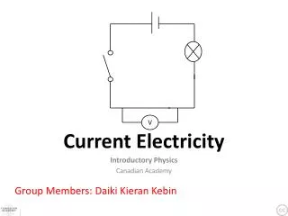
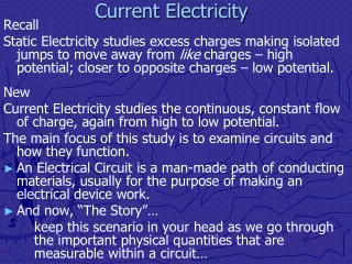
Current Electricity. 11.1 Electric Current. Circuit – continuous conducting path between terminals of a battery (or other source of EMF) Electric Current – flow of charge (electrons) I – current (amperes) Q – charge (coulomb) T – time. 11.1 Electric Current. Ampere (for Andre’ Ampere)

E N D
Circuit – continuous conducting path between terminals of a battery (or other source of EMF) Electric Current – flow of charge (electrons) I – current (amperes) Q – charge (coulomb) T – time 11.1 Electric Current
Ampere (for Andre’ Ampere) Usually called an amp Open Circuit – break in the circuit, no current flow 11.1 Electric Current
Short Circuit – when the load is bypassed Current increase Ground – allows for a continuous path for charge flow 11.1 Electric Current
For historical reasons, current is defined as being in the direction that positive charge flows 11.1 Electric Current
George Simon Ohm The actual values depend on the resistance of the conductor Called Ohm’s Law R – resistance measured in Ohms (W) 11.3 Resistance and Ohm’s Law
Resistor – anything that uses electric energy Resistor – device used to control current The symbol for a resistor is 11.3 Resistance and Ohm’s Law
The resistance value of a resistor is indicated by the colored bands on the resistor 11.3 Resistance and Ohm’s Law
Misconceptions • Cells (batteries) do not put out a constant current. They maintain a constant potential difference. • Current passes through a wire and depends on the resistance of the wire. Voltage is across the ends of the wire. • Current is not a vector, it is always parallel to the conductor. The direction is from + to -. 11.3 Resistance and Ohm’s Law
Misconceptions 4. Current or charge do not increase or decrease. The amount of charge in one end of the wire comes out of the other end. 11.3 Resistance and Ohm’s Law
An element or compound that conducts electricity without resistance Become insulators above a critical temperature Uses MagLev Trains 11.5 Superconductors
The rate of energy flow for an electric circuit That is more commonly written as Combining with Ohm’s Law it can also be written 11.6 Electrical Energy and Power
The power company charges by the kilowatt-hour (kWh) Just a cool picture 11.6 Electrical Energy and Power
Household circuits – wires will heat up as current increases In a 20A household circuit In a 15A household circuit Circuits are typically designed to run at 80% of the rated power output Different circuits have different gauge wires (diameter) 11.6 Electrical Energy and Power
Circuit Breakers and Fuses Break the circuit 11.6 Electrical Energy and Power
EMF – electromotive force – the potential difference between the terminals of a source when no current flows to an external circuit (e) 11.7 Sources of EMF
A battery will have an internal resistance (r) So there is a potential drop due to the current that travels through the cell So the actual potential across the terminals of a cell will be This is called the terminal voltage 11.7 Sources of EMF
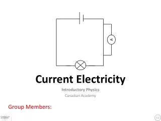
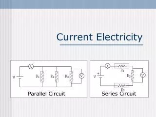
When resistors are place in a single pathway They are said to be in series A schematic would look like this 11.7 Sources of EMF
The current in a series circuit is the same throughout the circuit The potential across the source of EMF is equal to the sum of the potential drops across the resistors 11.7 Sources of EMF
Since potential can be defined as We can rewrite the equation for potential as 11.7 Sources of EMF
When resistors are place in a multiple pathways They are said to be in parallel A schematic would look like this 11.9 Resistors in Parallel
The potential difference in a parallel circuit is the same throughout the circuit The current through the source of EMF is equal to the sum of the current through the resistors 11.9 Resistors in Parallel
Since current can be defined as We can rewrite the equation for potential as 11.9 Resistors in Parallel
Circuits that contain both series and parallel components need to be solved in pieces This circuit contains 20W resistors in series 25W resistors and load series to each other and parallel to the 40W resistor 11.9 Resistors in Parallel