
Introduction to Hydraulic Systems Training
Learn about the fundamentals of hydraulic systems, including fluid power, basic principles, and different types of hydraulic motors. Develop the skills to work with hydraulic systems in various applications.

Introduction to Hydraulic Systems Training
E N D
Presentation Transcript
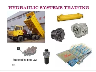
HYDRAULIC SYSTEMS TRAINING Presented by: Scott Levy Date
Introduction to Hydraulic Systems What are hydraulics? Answer – The study of the mechanical properties of fluids What is Fluid Power? Answer – The use of fluid motion under pressure to transfer power & energy from a source to a sink (receptor). Commercial Definitions: Hydraulics – The transmission of power from a power generation source to a sink using an engineered incompressible hydraulic fluid for the sake of creating leverage or motion. Pneumatics - The transmission of power from a power generation source to a sink using pressurized air (compressible) as the fluid for the sake of creating leverage or motion. THIS COURSE WILL ADDRESS HYDRAULIC FLUID POWER
Basic Hydraulic Fluid Principles Elements of Fluid Mechanics Fluid Flow = Q Volumetric rate gal/hour, L/min Fluid Pressure = P Force per square area Lbs/sq in, Kg/sq m Fluid Velocity = V Distance over time ft/sec, m/sec Fluid Temperature = T °F or °C Fluid Viscosity = ν Fluid resistance to flow cSt (centistokes)
Basic Hydraulic Fluid Principles Fluid Mechanics Relationships Flow – Velocity Q= A * v Where Q= Volumetric Flow Rate, A= Cross sectional Area & v= Fluid Velocity Fluid flow in a system is additive Bernoulli’s Law for incompressible fluids H = z + p/ρg + v2/2g (fluid is flowing with a significant difference in height between source & sink) Where H=total head pressure, v= fluid velocity, g= force of gravity, z= the height of the fluid source, p=fluid pressure & ρ=fluid density p0= p + v2/2 (fluid height is insignificant) Where p0 = total system pressure, p= static pressure v= flow velocity
Basic Hydraulic Fluid Principles Hydraulic Fluid Power Fluid power depends on a viscous fluid flowing under pressure from a sink to a source. The systems efficiency is dependent on fluid density, temperature and pressure loss due to decreased fluid velocity. Gravity Change in Temperature Source Creates Pressure Fluid Flow Viscous Fluid Has Velocity Sink Turns fluid pressure / energy into leverage
Basic Hydraulic Systems Overview Typical Lift / Ram Circuit (mobile or industrial – open center system) Cylinder Motion Relief Valve Control Valve Cylinder Pump Filter Tank Cooler
Basic Hydraulic Systems Overview Typical Motor Power Circuit (mobile – closed center system) EH Servo Control Valve Hydraulic Motor Blower Fan Joystick Variable Pump Filter Tank Cooler
Hydraulic Motors Hydraulic Motors Overview Purpose A hydraulic motor converts hydraulic energy from pressure into rotary motion and torque to drive an implement or system. Types • Fixed positive displacement – gear, piston, geroter / geroler & vane types • Variable positive displacement – piston Typical Applications • Wheel Motors – drive mobile equipment wheels (skid steers, tractors, lifts) • Fan Drives – hydraulic fan drives (engine cooling, industrial equipment, drive train cooling, gen sets, grain driers) • Industrial Machinery – (conveyers, machine tools, cutters, cranes, augers, winches) • Agricultural Equipment – Harvesters, Trenchers, Lawn Mowers, Forestry Equipment
Hydraulic Motors Fixed Positive Displacement Motors Motor displacement is fixed Torque is proportional to inlet pressure Speed is proportional to flow rate Regulate torque and speed with either valves, variable displacement pump or pump speed. Gear Motors • Inlet flow / pressure rotates a gear set causing the output shaft to rotate and create torque • Advantages • Low cost – initial and rebuild • Good availability / many suppliers • Cast iron motors have high pressure capability • Tolerant to contamination • Compact - desirable packaging • Disadvantages • Lower efficiency compared to other types • Lower torque per unit displacement compared to piston or Geroter / Geroler types
Hydraulic Motors Fixed Positive Displacement Motors Fixed Displacement Piston Motors • Axial Piston, Radial Piston & Bent Axis Types • Swash plate is fixed on an angle to achieve a specified displacement • Number & size of pistons in rotating group determine flow, torque and speed capabilities • Advantages • High efficiency / Performance • Higher torque capability per unit displacement • Radial type packages well for wheel motor applications • Bent axis type available for improved packaging • Good serviceability • Disadvantages • Higher cost • Not as tolerant to contamination Fixed Displacement Radial Piston Motor Fixed Displacement Bent Axis Piston Motor Fixed Angle Swash Plate Piston Rotating Group Fixed Displacement Axial Piston Motor
Hydraulic Motors Fixed Positive Displacement Motors Fixed Displacement Vane Motors • Fluid flow over vanes produce rotational speed and torque • High speed and pressure capability • Number & area of vanes determine flow, torque and speed capabilities • Advantages • High efficiency / Performance • Higher speed capacity • Reliability & durability • Forward or reverse rotation • Superior cold start performance • Good power output per motor size • Disadvantages • Lower torque capability • Higher cost than gear motors
Hydraulic Motors Fixed Positive Displacement Motors Fixed Displacement Geroter / Geroler Motors • Spool valve, disc valve & valve in star types • Low speed and high torque capability • Works on the “Orbit Principle” – star, drive and output shaft • Gerotor & Geroler have similar performance characteristics for equal frame sizes. In the Geroler type, the drive gear rides on roller bearings in the star for reduced friction, improved mechanical efficiency and useful life. • Advantages • High efficiency • Higher torque capacity • Reliability & durability – only three main components • Compact with high power density • Can be connected in series with same pump source • High systems pressure capability • Low speed constant with change in load • Disadvantages • No high speed applications • High cost than other motors
Hydraulic Motors Variable Positive Displacement Motors Variable Displacement Piston Motors • Axial Piston, Radial Piston & Bent Axis Types • Swash plate angle is variable – manual, hydraulic, EH or electric control • Number & size of pistons in rotating group determine flow, torque and speed capabilities • Advantages • High efficiency / Performance • Higher torque capability per unit displacement • Radial type packages well for wheel motor applications • Bent axis type available for improved packaging • Good serviceability • Disadvantages • Higher cost • Not as tolerant to contamination Variable Displacement Radial Piston Motor Variable Displacement Axial Piston Motor
Hydraulic Motors How to Choose & Size a Hydraulic Motor Step 1 – Document Motor Requirements • What is the application (wheel drive, fan, auger, winch, machine tool, turf care, etc.) • Space requirements - packaging • What torque is required for driving the application component? • What hydraulic system pressure is available to the motor? • What hydraulic system flow is available to the motor? • What speed range is required for the motor? • Does the motor have to stall or reverse direction? • What is the hydraulic oil cleanliness levels? • What are the cost factors? • How many motors will be run in series off of the same source? • What is the ambient temperature range of operation? • What hydraulic fluid will be used? Step 2 – Choose the Motor Type • Fixed or variable displacement? • If fixed displacement – use the motor type selection chart to determine which type of fixed displacement motor best meets the requirements.
Hydraulic Motors How to Choose & Size a Hydraulic Motor Fixed Motor Type Selection Chart
Hydraulic Motors How to Choose & Size a Hydraulic Motor Step 3 – Determine Motor Displacement • How much max horsepower or torque is required to drive the devise? Torque (in-lbs) = 63024 Horsepower / Speed (rpm) • What max displacement is required? Displacement (cubic in/rev) = 2π* Torque (in-lbs) / Δ Pressure (psi)* Mechanical Efficiency (%) Mechanical efficiency varies from 80-90% depending on the type of motor. • What flow is required at the motor? Flow (gpm) = Motor Displacement (cubic in / rev)* Speed (rpm) / 231* Volumetric Efficiency (%) Volumetric efficiency varies from 85-95% depending on the type of motor. Step 4 – Determine the motor that meets the requirements • Find a supplier that makes a motor of the type and size determined • Determine the best model motor to meet all or as many of the requirements for the application that is at least equal to or larger than the displacement calculated. • Compare the selected motor specifications to the motor requirements and qualify it for the application. • Recalculate the motor torque and flow with the selected motor’s specs to ensure the torque and system flow requirements are satisfied.
Hydraulic Motors How to Choose & Size a Hydraulic Motor Motor Sizing Example A hydraulic motor is needed to power a blower fan for a combine separation system. The fan speed will vary from 0 to 1500 rpm and the fan requires 15 hp at max speed and load conditions. The system pump supplying flow is a variable displacement axial piston pump with a max flow of 30 gpm. What type of motor and displacement will satisfy these requirements? Requirements: • Pressure available at the motor inlet = 2000 psi • Max pressure for motor return to tank = 100 psi • Clockwise rotation only • Only one motor in the system • System is unfiltered • Low cost is important • Ambient temp range 0 °F to 110 °F. • Hydraulic fluid – Hydraulic Oil w/viscosity at 15 cST normal operation, 10 cST min Motor Type – See selection chart Gear type is best selection Reasons – fixed displacement, low cost, tolerant to contamination in an unfiltered system & low pressure.
Hydraulic Motors How to Choose & Size a Hydraulic Motor Fixed Motor Type Selection Chart
Hydraulic Motors How to Choose & Size a Hydraulic Motor Motor Sizing Example Continued Theoretical Motor Displacement Calculation • Torque (in-lbs) = 63024 Horsepower / Speed (rpm) Torque = 63024 (15 hp) / 1500 rpm = 630 in-lbs • Δ Pressure (psi) = Max systems pressure @ inlet – Max motor return to tank pressure Δ Pressure = 2000 psi – 100 psi = 1900 psi • Displacement (cubic inch / rev) = 2π* Torque (in-lbs) / Δ Pressure (psi)* Mechanical Efficiency (%) Gear pump mechanical efficiency = 85% Displacement = (2π * 630 in-lbs) / (1900 psi * 0.85) = 2.45 cubic in/rev or 40.1 cc/rev Gear pump supplier chosen is Sauer Danfoss Group 3 frame size 44 • Specs vs. Requirements
Hydraulic Motors How to Choose & Size a Hydraulic Motor Motor Sizing Example Continued Verify actual motor torque Torque (in-lbs) = Δ Pressure (psi)* Mechanical Efficiency (%) * Displacement (cubic in/rev) / 2π • Torque = (1900 psi * 0.85 * 2.69) / 2π = 691 in-lbs > 630 in-lbs Verify actual motor flow Flow (gpm) = Motor Displacement (cubic in / rev)* Speed (rpm) / 231* Volumetric Efficiency (%) Volumetric Efficiency = 88% Flow = (2.69 cubic in/rev * 1500 rpm) / (231 * 0.88) = 19.8 gpm < 30 gpm available at the pump. THE PUMP SELECTED MEETS ALL THE REQUIREMENTS
Hydraulic Cylinders Hydraulic Cylinders Overview Purpose A hydraulic cylinder converts hydraulic energy from pressure into linear motion and force to actuate, move or lift an implement or object. Types • Dual Acting / Single Acting • Multi-stage Telescoping • Pressurized struts – Mobile Applications • Head & Cap Arrangements • Welded – Medium duty applications / size • Threaded – Light duty applications / size • Bolted – Heavy duty applications / size Suspension Strut Cylinder Cut Away Telescoping Cylinder Threaded Head Cylinder Welded Cylinder Bolted Cylinder
Hydraulic Cylinders Hydraulic Cylinders Overview Typical Applications • Construction Equipment – (implements, dump trucks, suspension struts, stabilizers, steering systems) • Lifts – (scissors lifts, aerial lifts, cranes, fork lifts, lift gates) • Industrial Machinery – (presses, rams, loading docks, injection molding machines) • Agricultural Equipment – (tractor implements, bailers, combine heads, sprayers) • Mining Equipment – (hoist, bucket, suspension struts, steering system, grader blades)
Hydraulic Cylinders Hydraulic Cylinders Overview Single vs. Dual Acting Cylinders • Single acting cylinder only actuates the rod • The rod extends under pressure and contracts under force or weight • Typically used in applications where load is lifted hydraulically and gravity returned • A spring in the system can be used to achieve contraction • Dual acting cylinder actuates the rod and the head ends • Both extension and contraction occur under hydraulic pressure • Typically used in applications where motion is not in the direction of gravity Single Acting Cylinder Dual Acting Cylinder
Typical Cylinder Construction Barrel or body Rod Piston & Seal Rod Gland Hydraulic Cylinders Hydraulic Cylinders Overview • Head • Cap • Position Sensor Position Sensor Rod Gland Head Barrel Cap Piston Rod
Hydraulic Cylinders How to Choose & Size a Hydraulic Cylinder Step 1 – Document cylinder requirements • What is the application (lift, press, steering, hoist, implement, ram, crane etc.) • Space requirements – packaging & end attachments • What is the max collapsed length • What is the max extended length • What max force or weight is necessary to actuate the attached object? • What hydraulic system pressure is available to the cylinder? • What hydraulic system flow is available to the cylinder? • How many cylinders will be used to move the load • What max time is required to go from min length to max extended length? • What are the cost factors? • What is the ambient temperature range of operation? • What hydraulic fluid will be used? Step 2 – Choose the cylinder type • Dual or Single Acting? • Single Stage or Multiple Stage Telescoping?
Hydraulic Cylinders How to Choose & Size a Hydraulic Cylinder Step 3 – Determine cylinder bore size • Force = Required Force / # Cylinders • Cylinder Bore (in) = [.7854 * Force (lbs) / Pressure (psi)] ½ • This is the minimum bore size required. To decrease the time to fully extend the cylinder, the bore size can be increased. • Find a Cylinder of the type chosen with the next larger bore size available Step 4 – Determine if the flow rate required for max extension . • Flow Rate (gpm) = Fluid Velocity (ipm) * Cylinder Piston Area (in) * 0.00433 • Cylinder Piston Area = π * [Cylinder Bore (in) / 2] 2 • Fluid Velocity (ipm) = [Extended Cylinder Stroke (in)] / [Max Extension Time (sec) / 60] • Is Flow Rate equal to or less than the required flow rate? If not, the cylinder bore size has to be increased to ensure the max time to full extension is satisfied within the flow rate available. Step 5 – Determine the piston rod diameter & column size • Determine the column strength factor from Table 1.1 • Corrected Length = Actual Stroke * Column Strength Factor • Cylinder Thrust (lbs) = Max System Relief Pressure (psi) * Cylinder Piston Area
Hydraulic Cylinders How to Choose & Size a Hydraulic Cylinder Step 5 – Determine the piston rod diameter & column size continued • Determine the appropriate piston rod diameter using Table 1.2 • Determine the stop tube length if necessary • Internal stops are sometimes required to limit rod stroke to prevent rod buckling • Stop Tube Length (in) = [Corrected Length – 40 in] / 10
Hydraulic Cylinders How to Choose & Size a Hydraulic Cylinder Step 6 – Choose the type of cylinder ends for attachment Step 7 – Determine a cylinder that meets the requirements • Find a supplier that makes a cylinder of the type and size determined • Determine the best model cylinder to meet all or as many of the requirements for the application that is at least equal to or larger than the bore and rod diameter calculated. • Compare the selected cylinder specifications to the cylinder requirements and qualify it for the application. • Recalculate the cylinder load capability and time for full extension with the selected cylinder’s specs to ensure that these requirements are satisfied.
Hydraulic Cylinders How to Choose & Size a Hydraulic Cylinder Cylinder Sizing Example A cylinder is needed to lift and lower a dump truck bed. The design calls for two cylinders. The maximum load that the cylinders have to lift is 58,350 Lbf. The maximum stroke is 70 inches. The maximum time to fully extend the cylinders into the full dump position is 12 seconds. The system relief pressure is set to 2400 psi and the max available flow rate is 25 gal/min. The empty dump bed weight is not enough to fully retract the cylinder. Requirements: • Max fully extended length – 125 inches • Max fully retracted length – 42 inches • Clevis Pivot Mount • System is filtered • Ambient temp range 0 °F to 110 °F. • Hydraulic fluid – Hydraulic Oil w/viscosity at 15 cST normal operation, 10 cST min Cylinder Type Telescoping dual acting cylinder is chosen Reason – the fully extended length is more than ½ the fully retracted length and hydraulic pressure is needed to fully lower the dump bed.
Hydraulic Cylinders How to Choose & Size a Hydraulic Cylinder Cylinder Sizing Example Continued Cylinder Bore Size • Force = Required Force / # Cylinders = 58,350 lbs / 2 Cylinders = 29,175 Lbs • Cylinder Bore (in) = [.7854 * Force (lbs) / Pressure (psi)] ½ Cylinder Bore = [.7854 * 29175 / 2400] ½ = 3.09 inches Standard multistage cylinder has bores – 4.5” 1rst stage, 3.5” 2nd stage & 2.5” 3rd stage and is capable of supporting up to 30,000 Lbs static load. Determine if the flow rate required for max extension. • Cylinder Piston Area = π * [Cylinder Bore (in) / 2] 2 Stage 1 piston Area = π * [4.5 (in) / 2] 2 = 15.9 sq in (largest section) • Fluid Velocity = [Extended Cylinder Stroke (in)] / [Max Extension Time (sec) / 60] Fluid Velocity = [ 70 in ] / [12 / 60] = 350 in / min • Flow Rate (gpm) = Fluid Velocity (ipm) * Cylinder Piston Area (sq in) * 0.00433 Flow Rate = 350 in/min * 15.9 sq in * 0.00433= 24.1 gal / min < 25 gal / min Determine the piston rod diameter & column size • From Table 1.1 the Column Strength Factor = 2.0
Hydraulic Cylinders How to Choose & Size a Hydraulic Cylinder Cylinder Sizing Example Continued Determine the piston rod diameter & column size • From Table 1.1 the Column Strength Factor = 2.0 • Corrected Length = Actual Stroke * Column Strength Factor = 70 in * 2.0 = 140 in • Cylinder Thrust (lbs) = Max System Relief Pressure (psi) * Cylinder Piston Area Cylinder Thrust = 2400 psi * 15.9 sq in = 38,160 lbs • Use Table 1.2 to determine the minimum rod diameter Stop Tube Length (in) = [Corrected Length – 40 in] / 10 = [140 -40] / 10 = 10 in Cylinder ends – ClevisPivot Mount Piston Rod Diameter = 4.5 in Corrected Length =140 in Thrust Load =38,160 Lbs
Hydraulic Cylinders How to Choose & Size a Hydraulic Cylinder Cylinder Sizing Example Continued Determine a cylinder that meets the requirements • The supplier chosen is Prince – PMC/SAE 62 a 3-stage telescoping cylinder with 5”x4”x3” rod sizes and 5.5”x4.5”x3.5” bore sizes.
Hydraulic Cylinders How to Choose & Size a Hydraulic Cylinder Cylinder Sizing Example Continued Determine a cylinder that meets the requirements • Cylinder time to full extension • Recalculate the cylinder load capability and time for full extension with the selected cylinder’s specs to ensure that these requirements are satisfied.


![[Date]](https://cdn2.slideserve.com/4327049/slide1-dt.jpg)
![[ Date ]](https://cdn2.slideserve.com/5349218/slide1-dt.jpg)
![[date]](https://cdn3.slideserve.com/5623089/slide1-dt.jpg)

![[Date] Next Review [Date]](https://cdn3.slideserve.com/6646950/date-next-review-date-dt.jpg)