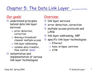
Chapter 5: Link and Physical Layers in Computer Networks
This chapter provides a comprehensive overview of the link and physical layers in computer networks. It includes an introduction to services, error detection and correction mechanisms, and various link access protocols. The chapter further explores Ethernet, its model and frame structures, as well as LAN addresses and ARP. It also discusses Ethernet technologies and networking devices like hubs, bridges, and switches. The importance of link layer services such as reliable delivery and flow control is emphasized, alongside a practical analogy for understanding communication links.

Chapter 5: Link and Physical Layers in Computer Networks
E N D
Presentation Transcript
Shahrood University of TechnologyDepartment of Computer Engineering & IT Computer Networks Link & Physical Layers
Chapter 5 outline 5.1 Introduction and services 5.2 Error detection and correction 5.3 Links and Access Protocols 5.4 Ethernet 5.5 Ethernet Model 5.6 Ethernet Frame Structure 5.7 LAN addresses and ARP 5.8 Ethernet Technologies 5.9 Hubs, bridges, and switches 5.10 Point to Point Protocol
Link Layer: Introduction Some terminology: hosts and routers are nodes (bridges and switches too) communication channels that connect adjacent nodes along communication path are links wired links wireless links LANs PDU: frame,encapsulates datagram network data link physical network data link physical network data link physical application transport network data link physical application transport network data link physical modem modem network data link physical “link” link layer has responsibility of transferring datagram from one node to adjacent node over a link.
Layers Application Software Application protocols (softwares) TCP/IP Protocol Stack Transport Protocols (softwares) Network(Internetwork) Protocols (softwares) Logical Link Control Protocols (software) Link & Physical Protocols (Software + Hardware) Medium Access Control Protocols (Hardware) Physical Protocols (Hardware) Ethernet, Token Ring, Token Bus FDDI, ...,
Link layer: context tourism analogy: trip from Tehran to Toos taxi: Tehran to Mehrabad Airport plane: Mehrabad to Mashhad bus: Mashhad to Toos tourist = datagram taxi, plane, bus = communication link transportation mode = link layer protocol tour agent = routing algorithm Datagram transferred by different link protocols over different links: e.g., Ethernet on first link, frame relay on intermediate links, 802.11 on last link Each link protocol provides different services e.g., may or may not provide reliable data transfer (rdt) over link
Physical Frame Transfer Frame: Src IP Add=A Dst IP Add=S Src LAN Add=LR13 Dst LAN Add=LR22 Frame: Src IP Add=A Dst IP Add=S Src LAN Add=B Dst LAN Add=LR12 Frame: Src IP Add=A Dst IP Add=S Src LAN Add=LR42 Dst LAN Add=T router1 to router2 client to router1 router4 to server IP Add: IR22 LAN Add: LR22 IP Add: A LAN Add: B IP Add: IR11 LAN Add;LR12 router2 Ethernet, 10Mbps client ppp, 33.3kbps router1 router3 IP Add: IR13 LAN Add: LR13 IP Add: IR42 LAN Add: LR42 router4 IP Add: S LAN Add: T Fast ethernet LAN Add: 48 bit(6 × 8bit) (example: 74-29-9C-E8-FF-55) server
Link Layer Services Link layer header Network layer datagram Link layer trailer Layer 2 PDU: Frame • Framing, link access: • encapsulate datagram into frame, adding header, trailer • channel access if shared medium • ‘physical addresses’ used in frame headers to identify source, destination. • different from IP address! • Reliable delivery between adjacent nodes • we learned how to do this already (chapter 3)! • seldom used on low bit error link (fiber, some twisted pair) • wireless links: high error rates • Q: why both link-level and end-end reliability?
Link Layer Services (more) • Flow Control: • pacing between adjacent sending and receiving nodes • Error Detection: • errors caused by signal attenuation, noise. • receiver detects presence of errors: • signals sender for retransmission or drops frame • Error Correction: • receiver identifies and corrects bit error(s) without resorting to retransmission • Half-duplex and full-duplex • with half duplex, nodes at both ends of link can transmit, but not at same time
Adaptors Communicating link layer implemented in “adaptor” (NIC) Ethernet card, PCMCI card, 802.11 card sending side: encapsulates datagram in a frame adds error checking bits, rdt, flow control, etc. receiving side looks for errors, rdt, flow control, etc extracts datagram, passes to receiving node adapter is semi-autonomous link & physical layers frame frame datagram receiving node link layer protocol sending node adapter adapter
Chapter 5 outline 5.1 Introduction and services 5.2 Error detection and correction 5.3 Links and Access Protocols 5.4 Ethernet 5.5 Ethernet Model 5.6 Ethernet Frame Structure 5.7 LAN addresses and ARP 5.8 Ethernet Technologies 5.9 Hubs, bridges, and switches 5.10 Point to Point Protocol
Error Detection • EDC= Error Detection and Correction bits (redundancy) • D = Data protected by error checking, may include header fields • Error detection not 100% reliable! • protocol may miss some errors, but rarely • larger EDC field yields better detection and correction
Internet checksum Sender: treat segment contents as sequence of 16-bit integers checksum: addition (1’s complement sum) of segment contents sender puts checksum value into UDP or TCP checksum field. Receiver: compute checksum of received segment check if computed checksum equals checksum field value: NO - error detected YES - no error detected. But maybe errors nonetheless? More later …. Goal: detect “errors” (e.g., flipped bits) in transmitted segment (note: used at transport layer only)
Checksumming: Cyclic Redundancy Check bit pattern D: data bits to be sent R: CRC bits mathematical formula: [D×2rXOR R] r [bits] d [bits] • view data bits, D, as a binary number • choose r+1 bit pattern (generator), G • goal: choose r CRC bits, R, such that • <D,R> exactly divisible by G (modulo 2= add without carry) • receiver knows G, divides <D,R> by G. If non-zero remainder: error detected! • can detect all burst errors less than r+1 bits • widely used in practice (ATM, HDCL)
CRC Example 101110000 1001 1001 101011 101 000 1010 1001 110 000 1100 1001 1010 1001 011 D×2r G = D×2r G R = remainder[ ] R D=101110, G=1001 r=3, D×2r=101110000 want: D×2rXOR R = n×G equivalently: D×2r = n×G XOR R equivalently: if we divide D×2r by G, want remainder R
Ethernet CRC • Polynomial Presentation • Based on use of polynomial codes • Message frame and Generator thought of as binary polynomials • Example: 101101101 ~ x8 + x6 + x5 + x3 + x2 + x0 • Ethernet CRC • It is a CRC-32: It is 33 bit code that is uses as Generator: • G(x) = x32 + x26 + x23 + x22 + x16 + x12 + x11 + x10 + x8 + x7 + x5 + x4 + x2 + x + 1
CRC Properties • Detect all single-bit errors if coefficients of xr and x0 of G(x) are one • Detect all double-bit errors, if G(x) has a factor with at least three terms • Detect all number of odd errors, if G(x) contains factor (x+1) • Detect all burst of errors smaller than r bits
Chapter 5 outline 5.1 Introduction and services 5.2 Error detection and correction 5.3 Links and Access Protocols 5.4 Ethernet 5.5 Ethernet Model 5.6 Ethernet Frame Structure 5.7 LAN addresses and ARP 5.8 Ethernet Technologies 5.9 Hubs, bridges, and switches 5.10 Point to Point Protocol
Types of “links”- Point to Point modem modem • point-to-point • PPP for dial-up access • point-to-point link between Ethernet switch and host Router LAN Switch Telephone Lines External Link Remote Access Server Modem pools hub Client Servers Client Server Client Printer Client point-to-point link between LAN switch and hosts. PPP for dial-up access
Types of “links”-Broadcast terminator terminator • broadcast (shared wire or medium) • traditional Ethernet (coaxial bus, hub) • 802.11 wireless LAN • upstream Hybrid Fiber Coaxial • Efficiency: Low Latency & High Throughput [in average]
Ideal Broadcast Channel Access Protocol • Broadcast channel of rate R bps • When one node wants to transmit, it can send at rate R. • When M nodes want to transmit, each can send at average rate R/M • Fully decentralized: • no special node to coordinate transmissions • no synchronization of clocks, slots • Simple
Broadcast Classes • Channel Partitioning • divide channel into smaller “pieces” (time slots, frequency, code) • allocate piece to node for exclusive use • Random Access • channel not divided, allow collisions • “recover” from collisions • “Taking turns” (Token/Polling) • tightly coordinate shared access to avoid collisions
Random Access Protocols • When node has packet to send • transmit at full channel data rate R. • no a priori coordination among nodes • two or more transmitting nodes -> “collision”, • random access MAC protocol specifies: • how to detect collisions • how to recover from collisions (e.g., via delayed retransmissions) • Examples of random access MAC protocols: • slotted ALOHA • ALOHA • CSMA, CSMA/CD, CSMA/CA
ALOHA (Pure, Slotted) • All frames same size • Slotted: Time is divided into equal size slots • 1 slot = time to transmit 1 frame • Pure: Time remains continues • Slotted: Nodes start to transmit frames only at beginning of slots • Pure: Nodes start to transmit whenever a frame is made. • Slotted: Nodes are synchronized • Pure: Nodes are not synchronized • If 2 or more nodes transmit in slot, all nodes detect collision
Slotted Aloha Efficiency Suppose N nodes with many frames to send, each transmits in slot with probability p probability that first node has success in a slot= p(1-p)N-1 probability that any node has a successis=Np(1-p)N-1 For max efficiency with N nodes, find pm that maximizes Np(1-p)N-1 For many nodes, take limit of N pm(1- pm)N-1as N goes to infinity, gives 1/e = 0.37 At best: channel used for useful transmissions 37% of time!
Pure Aloha Mosel-1 SupposeF:the average frame length, R: bandwidth, TF=F/R:frame time Transmit a frame att=t0(and finish transmission of the frame att0+TF) frame transmission time t0 t0+TF t0-TF Vulnerable period Vulnerable period: if any other frames are transmitted during the period, the collision will occur. Therefore the probability of a successful transmission is the probability that there is no additional transmissions in the vulnerable period.
Pure Aloha Mosel-2 t t t • Poisson model: probability of k frames transmission attempts in t time units. Time unit = 1 frame Time = F/R • G=Offered Load [Frames/Time unit] • infinite population model: (too many senders each with too many frames to transmit. …… time The green frame dose not experience collision if during Vulnerable period no one tries to transmit a frame:
Throughput vs Offered Load- Pure Aloha • The throughput S is given by:
Slotted ALOHA Model • Synchronize the transmissions of stations • All stations keep track of transmission time slots and are allowed to initiate transmissions only at the beginning of a time slot. • Suppose a packet occupies one time slot • Vulnerable period is fromt0-TFtot0, i.e.,TF seconds long. • Therefore, the throughput of the system is:
S-G Graphs-1 0.37 Slotted ALOHA S =Throughput [Frame/Time unit] 0.18 (pure) Non-slotted ALOHA 0.5 G =Offered Load [Frame/Time unit]
S-G Graphs-2 Slotted ALOHA S =Throughput [Frame/Time unit] (pure) Non-slotted ALOHA S=kG G =Offered Load [Frame/Time unit]
Collision Control Controlled Throughput Uncontrolled Offered load Lack of collision control
CSMA (Carrier Sense Multiple Access) CSMA: listen before transmit: • If channel sensed idle: transmit entire frame • If channel sensed busy, defer transmission
CSMA Collisions terminator terminator A B C D collisions can still occur: propagation delay means two nodes may not hear each other’s transmission t0 t1 collision: entire packet transmission time wasted Collision Detection Times Frame transmission time note: role of distance & propagation delay in determining collision probability time distance
CSMA collisions A B C D t0 t1 TAD TF TF ‹ (TAD+TDA) = 2×TAD TDA Collision Detection Time=0 time distance collision occurs: A finishes transmitting a frame, then receives D’s frame so A cannot detect the collision. Collision detection condition: TF: Frame transmission Time [sec] TAD: A to D propagation time [sec] Then: TF≥ 2×TAD F: Frame length [bit] R: Transmission Rate (Bandwidth) [bit/sec] —› TF=F/R d: A to D distance [m] V: signal propagation velocity in channel [m/sec] —› TAD= d/V TF ≥ 2×TAD —› F ≥ 2×R×TAD—› α=TAD/(F/R) ≤ 0.5
Summary of MAC protocols • What do you do with a shared media? • Channel Partitioning, by time, frequency or code • Time Division,Code Division, Frequency Division • Random partitioning (dynamic), • ALOHA, S-ALOHA, CSMA, CSMA/CD • carrier sensing: easy in some technologies (wire), hard in others (wireless) • CSMA/CD used in Ethernet • Taking Turns • polling from a central site, token passing
Chapter 5 outline 5.1 Introduction and services 5.2 Error detection and correction 5.3 Links and Access Protocols 5.4 Ethernet 5.5 Ethernet Model 5.6 Ethernet Frame Structure 5.7 LAN addresses and ARP 5.8 Ethernet Technologies 5.9 Hubs, bridges, and switches 5.10 Point to Point Protocol
IEEE 802 LAN standards • One LLC and several MACs, each MAC has an associated set of physical layers. • MAC provides connectionless transfer. Generally no error control because of relatively error free. • Ethernet consists of 802.2 + 802.3 + a physical layer LLC MAC Figure 6.11
Ethernet “dominant” LAN technology: • Cheap even for 100Mbs! • First widely used LAN technology • Simpler, cheaper than token LANs and ATM • Kept up with speed race: 10, 100, 1000, 10000, 40000 Mbps Metcalfe’s Ethernet Sketch, 1973, Xerox.
Ethernet uses CSMA/CD No slots Adapter doesn’t transmit if it senses that some other adapter is transmitting, that is, carrier sense Transmitting adapter aborts when it senses that another adapter is transmitting, that is, collision detection Before attempting a retransmission, adapter waits a random time, that is, random access. Adapter keeps trying to transmit, that is, multiple access.
Ethernet CSMA/CD algorithm 1.Adaptor gets datagram and creates frame 2. If adapter senses channel idle, it starts to transmit frame. If it senses channel busy, waits until channel idle and then transmits 3. If adapter transmits entire frame without detecting another transmission, the adapter is done with frame ! 4.If adapter detects another transmission while transmitting, aborts and sends jam signal 5. After aborting, adapter enters exponential backoff: after the mth collision, adapter chooses a K at random from {0,1,2,…,2m-1}. Adapter waits K×512 bit times and returns to Step 2
Ethernet MAC flow in Half-Duplex Mode-Transmission Frame Ready for Transmission Exponential backoff Set Attempt N=0 wait R×512 bit times Sense Channel Select A Random Integer R=(0 to 2k-1) Channel Busy Yes No K=10 K=N Inter-frame Gap allows receivers time to settle yes No N<10 Wait Inter-frame Gap 9.6 μs Frame Transmission & Channel Sense Too Many Attempts? N<15 N=15 Abort Transmission; Send Jam Signal(3Bytes) Increment Attempts N++ Busy Collision Frame successfully transmitted Unsuccessful transmission, Excessive Collisions
Ethernet’s CSMA/CD (more) Bit time: 0.1 µsec for 10 Mbps Ethernet ;for K=1023, wait time is about 1023 ٭(0.1 ٭ 512)≈50 msec Jam Signal: makes sure all other transmitters are aware of collision; 32 bits; Exponential Backoff: Goal: adapt retransmission attempts to estimated current load heavy load: random wait will be longer first collision: choose K from {0,1}; delay is K x 512 bit transmission times after second collision: choose K from {0,1,2,3}… after next collision double K (and keep doubling on collisions until…..) after 10 collisions, choose K randomly from {0,1,2,3,4,…,1023}
Ethernet comments • Exponential Back off: upper bounding at K = 1023(210-1) limits max size. • could remember last value of K when we were successful (analogy: TCP remembers last values of congestion window size) • Q: why use binary back off rather than something more sophisticated such as TCP’s additive increase/multiplicative decrease (AIMD) -> simplicity (?) • note: Ethernet does multiplicative-increase-complete-decrease (why?) Increase the waiting probability range by 2m Decreasing the rang completely after getting through
Ethernet MAC flow in Half-Duplex Mode-Receive Receive Process Idle Channel Sense Busy Start Receiving Busy Channel Sense Idle Received Frame too Small? (Jam Signal) Yes No No Recognize Address? Yes Valid Frame Check Sequence? No No Extra bits? Yes Yes Successful Reception Receive Alignment Error Receive Frame Check Error
Ethernet’s use of randomization More collisions Heavier Load, more nodes trying to send Randomize retransmissions over longer time interval, to reduce collision probability
Chapter 5 outline 5.1 Introduction and services 5.2 Error detection and correction 5.3 Links and Access Protocols 5.4 Ethernet 5.5 Ethernet Model Ethernet and Randomization Ethernet Model (throughput, response time, efficiency) 5.6 Ethernet Frame Structure 5.7 LAN addresses and ARP 5.8 Ethernet Technologies 5.9 Hubs, bridges, and switches 5.10 Point to Point Protocol
Ethernet Model • An analytical model for Ethernet is developed. • The model includes • Throughput, • Response Time and • Efficiency (Utilization)
Model Assumptions • Large number of active nodes, with each node having a large number of frames to send. • Fixed length frames. • The packets transmission probability is Poisson. • Poisson model: probability of k packets transmission attempts in t time units • infinite population model
Model Parameters • Frame transmission time is unit of time (F/R). • ThroughputS - number of frames successfully (without collision) transmitted per unit time. • Offered loadG - number frames transmissions attempted per unit time. • Note:S <= G, S depends on G.
Throughput Model …… time idle time is a random variable given by I busy time is a random variable given by B collision time is a random variable given by C • The throughput S is given by: