Download

1 / 36
360 likes | 379 Views
Develops a hybrid-enabled fuel cycle to minimize nuclear waste impact. Fusion driver enhances fusion program elements and eases fusion technology requirements.

E N D
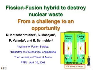
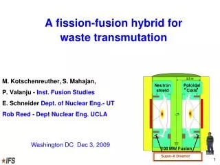
A fission-fusion hybrid for waste transmutation M. Kotschenreuther,S. Mahajan, P. Valanju - Inst. Fusion Studies E. Schneider Dept. of Nuclear Eng.- UT Rob Reed - Dept Nuclear Eng. UCLA Neutron shield Poloidal Coils 100 MW Fusion Super-X Divertor Washington DC Dec 3, 2009 1
Provide a solution to main public acceptability issue of nuclear fission with minimal perturbation of the present nuclear industry A hybrid-enabled fuel cycle so that a fleet of ~ 100 LWRs requires only about 5 hybrids for waste destruction A fusion driver that Dovetails and reinforces fusion program elements leading to pure fusion Minimizes issues of combining fission and fusion (potentially severe) Provides a practical application for fusion with much easier physics and technology requirements UT concept elements 2
~ 100 MW DT tokamak or Spherical Tokamak (ST) with conservative core physics (like ITER- H mode confinement, below no-wall limit) Main fusion extrapolation- high overall duty factor DT operation (ITER ~ 4%) Attaining such a high duty factor has many new challenges Adequate component lifetimes in the severe fusion environment 14 MeV neutron damage Plasma facing component erosion from long plasma exposure Rapid component replacement in highly radioactive, complex devices Large tritium breeding / throughput / handling Operation with very long pulses and very low disruption frequency More severe divertor challenges- Super-X divertor is a key Fusion driver for such a hybrid 3
Fusion Nuclear Facility (FNF) - formerly called a fusion Component Test Facility (CTF) We call the very similar hybrid driver a Compact Fusion Neutron Source (CFNS) Unlike ITER, a CFNS (or FNF) is not primarily self heated by fusion reactions- like present experiments it is primarily externally heated Hence, it is not necessary to await results from ITER self-heated plasmas Conservative physics suffices for the CFNS-FNF mission Hybrid driver is very similar to a Fusion Nuclear Facility 4
CFNS uses operating modes and dimensionless physics parameters where present experiments operate reliably (tokamaks & spherical tokamaks) Conservative Core Physics Demands • only because Super-X divertor allows high power density without degrading the core 5
“ITER in vessel components generally utilize materials, coolants and operating temperatures that do not extrapolate to reactor (or hybrid) conditions” A Fusion Nuclear Facility FNF will be needed to demonstrate availability growth before either a pure fusion reactor or a hybrid US and EU teams are developing normal coil FNF designs based on ST and tokamak Normal coils - a much more easily maintainable system- for high duty factor operation Device capitol cost- thick shielding of superconductors makes a device much larger at modest power levels ~ 100 MW (R = 3 - 4 meter vs 1.4-1.9 meter for normal coils) We propose using nearly the same design as the FNF as a driver for the hybrid- since the same advantages apply Coil electricity requirements- much less important with a high fission power boost, and a high support ratio of hybrids to LWRs (fusion ~ 0.2% of system power) Fusion development path 6
FNF is the first device in the fusion development path to have an overall duty factor higher than the low percents Present goal of FNF- 30% availability (considered a challenge even with normal coils!) Fission plants have an overall duty factor ~ 90% How might an early generation hybrid have a high plant duty factor? Duty factor is the key challenge 7
Fastest maintenance- replace components as large modules, and service them off-line ARIES-ST- replaced the 4000 ton fusion core (1st wall, blanket & centerpost) as a single unit Culham ST reactor study- replaced 800 ton centerpost Entire CFNS weight is ~ 400 tons (drained) Could replace CFNS components as a small number of modules or even as a single unit Use maintenance advantages of compact normal coil devices 8
Replaceable Fusion Module Concept A B • Whole CFNS issmall enough to fit inside fission blanket • Fission blanket is separate from fusion driver 9
Replaceable Fusion Module Concept A B • Put driver B into fission blanket • Use driver B while driver A is being refurbished off-line 11
Hybrid CFNS we propose has much less demanding requirements than FNF testing for DEMO Hybrid Neutron wall fluence ~ 2 MW yr / m2 Pure fusion DEMO requirement ~ 6 MW yr / m2 Component damage is ~ 3 times less Existing materials probably will suffice at ~2 MW yr / m2 Less material / design development and iteration needed compared to much more severe material degradation expected at ~ 6 MW yr/m2 Testing iterations to develop and prove reliability take ~ 3 times less time each (almost a decade less) Adequate reliability / availability adequate for a hybrid could be demonstrated much sooner than for a pure fusion DEMO Technology challenges for such a hybrid much less than for a pure fusion DEMO 12
Replaceable fusion driver Driver replaced up to yearly while fission fuel rods reshuffled (reduces development time, neutron damage) Damaged driver refurbished in remote maintenance bay (easier maintenance) Fission assembly is physically separate from fusion driver (failure interactions minimized) Fission assembly is electro-magnetically shielded from plasma transients by TF coils (disruption effects greatly reduced) Fission blanket is outside TF coils (coolant MHD drastically reduced) Modular concept addresses all these issues We shall now spell these out 13
The availability of each individual fusion driver is < 50%, while the hybrid availability is much higher Allows adequate hybrid availability with considerable less demanding fusion technology Neutron damage is ~ 3 times less than pure fusion DEMO CFNS: possible at an earlier level of fusion technology 14
The TF coils act as a “cage” to isolate the fission blanket from events in the fusion system The cage is strong: magnetic stresses are about an order of magnitude below the cage strength Electro-magntic disruption forces are less about half the static forces MCNP calculations fully include the cage geometry-fusion neutron losses are modest (~ 20%) Outer TF coil legs (Al) should last significantly longer than inner TF centerpost (Cu) CFNS: Isolates the fission blanket from off-normal fusion events using the TF coils as a strong “cage” 15
Calculations by UT Center for Electromechanics using 3D EM codes Disruptions: as fast as ~ 1 ms The thick conducting cage slows the disruption speed in the fission blanket to ~ 100 ms Electromagnetic forces in the fission blanket reduced by an order of magnitude Electromagnetic disruption effects on blanket 16
Fission blanket power density is much higher than pure fusion- MHD coolant problems could be very severe for a hybrid Magnetic field outside the TF coils is only from PF, and is almost exactly vertical- aligns almost perfectly with the coolant flow direction MHD drag effects reduced by ~ 2 orders of magnitude MHD coolant effects 17
A CFNS/CTF has high plasma power density - exhausting the plasma power harmlessly is crucial Power is exhausted as hot plasma and follows magnetic field lines to a divertor The plasma that hits the divertor cannot be at too high a temperature- or else: It quickly erodes through the divertor It sputters atoms off the wall into the plasma Very low helium ash exhaust ultimately choking off the fusion reaction A Standard Divertor (SD) - too hot Super-X Divertor (SXD)- allows exhaust to expand and cool Super-X Divertor Standard Divertor 18
Super-X Divertor (SXD) provides the desired operation - unlike the standard divertor SXD -Magnetic geometry is changed so exhausted hot plasma expands and cools Analysis using best available simulation (SOLPS - as for ITER) Standard divertor - exhausted high power plasma is unacceptable “sheath limited”- very hot and damaging SXD- exhausted plasma is desirable “partially detached”- what ITER design aims for T < 10- 20 eV Calculations by John Canik ORNL 19
The CFNS core plasma can operate conservatively- minimizing chances of disruptions Low plasma density allows strong plasma current to be driven controllably (ECCD, EBW, NB, HHFW)- with many benefits: Strong current enables low disruptivity H- mode confinement suffices, avoiding need for ITB with tricky control Operation below No-wall stability limit Operation well below density limit Operation with low plasma radiation 20
Rough gross metrics normalized to ITER = 1 Disruption severity- relative - CFNS main extrapolations: steady state and SXD 21
Summary UT hybrid scheme- uses plasma confinement schemes with the most highly developed physics basis - tokamaks and spherical tokamaks Super-X divertor allows operation in regimes with conservative physics and low disruptivity Employ the fusion driver as a replaceable module to enable higher availability with a nearer term stage of fusion technology development Fission blankets outside the TF coils enormously decouples the fission and fusion elements- speeding development and reducing safety issues 23
SXD-from theory to experiment Worldwide plans are in motion to test SXD MAST upgrade now includes SXD NSTX: XD and future SXD? DIII-D SXD test experiments, possibly next year Long-pulse superconducting tokamak SST in India designing SXD SXD for MAST Upgrade 24
Plasma Issues Reliable long pulse operation (high availability) with current drive and very low disruptions In the coming decade, experiments will address this: Tokamak - K-STAR, EAST- long pulse Spherical tokamak- NSTX/MAST upgrades RF current drive- how to drive a current profile with adequate MHD stability? Consider same technologies as ITER- ECCD, FW, NBI ECCD: most desirable- 2nd or 3rd harmonic is accessible-also EBW? Ion Cyclotron- High Harmonic Fast Wave Neutral beam- very undesirable for hybrid- avoid large penetrations of fission blanket Selenoid free start-up ~50 MW of EC should make this possible Plasma facing components for ~ 1 year exposure Lithium in porous substrate- promising possibility- NSTX? Density control for ST operation at low Greenwald Lithium pumping in NSTX and cryo-pumping in MAST Super-X Divertor Testing- MAST, NSTX, DIII-D, SST- others? 25
Properties and reliability of components damaged by 14 MeV neutrons High He generation Walls, magnets, RF antenna/wave guides, etc. Tritium retention/diffusion in CFNS components Maintenance: Can all coolant/power lines be from above/below for easy CFNS removal? How low can the CFNS replacement time be? Development of high current power supplies/bus for the magnet Magnet design window for neutron damaged Cu and Al Plasma disruption forces on CFNS and fission blanket PFC and fusion component cooling Fusion Technology Issues 26
CFNS Unknowns - Plasma wall interaction SXD is promising, but needs testing Success of SXD still leaves further PMI issues Tritium retention Effect of loss of wall conditioning on plasma performance? Will material surfaces evolve acceptably at long times (e.g., will erosion / re-deposition lead to wall flaking & plasma disruptions?) Will surfaces survive a rare disruption without unacceptable damage? Liquid metal on porous substrate looks like a promising potential solution to all of these NSTX might be able to test it sometime in the future? 27
Scientist and Businessman - A rare meeting of minds Jim Hansen - Tell Obama the Truth-The Whole Truth: • However, the greatest threat to the planet may be the potential gap between that presumption (100% “soft”energy) and reality, with the gap filled by continued use of coal-fired power. Therefore it is important to undertake urgent focused R&D programs in both next generation nuclear power and --- • However, it would be exceedingly dangerous to make the presumption today that we will soon have all-renewable electric power. Also it would be inappropriate to impose a similar presumption on China and India. Exelon CEO John Rowe Interview - Bulletin of American Scientists: • We cannot imagine the US dealing with the climate issue, let alone the climate and international security issues without a substantial increment to the nation’s nuclear fleet • I think you have to have some federal solution to the waste problem ---- If it (the Federal Government) ultimately cannot, I do not see this technology fulfilling a major role Renaissance of Fission Energy is emerging as a global imperative - everyone is talking! A believable technical solution to the nuclear waste problem- a scientific imperative
UT-Hybrid vs Fission-only Cycle Required Reactor fleets for zero net transuranic nuclear waste production from the current ~100 US utility reactors Under our proposal 4-6 new utility-scale hybrid reactors would suffice Waste reprocessing for fast-spectrum reactors will also be reduced by roughly an order of magnitude
Reactor Requirements for Waste Transmutation for different schemes Reactors needed to destroy waste from 100 LWRs FR cost = 1.5 LWR, Hybrid = 2 LWR
The ST has somewhat greater extrapolation than a conventional tokamak But, we believe the main extrapolation risk from today to a hybrid driver is in neutron damage and high duty factor- not physics Furthermore, we believe the ST has advantages in coupling to a fission blanket and in maintenance Hence, we have opted for the ST initially to ameliorate the technology risks through easier maintenance Size and B field Extrapolations 31
Time Scales US Plan for the development of fusion energy- CTF operating in 2023 UK- ST-CTF operating in 2026 Three independent groups working on CTFs world wide, to deliver ~ 1 MW/m2 in the time frame above: ORNL- Spherical tokamak (ST) General Atomic- advanced tokamak Culham- Sherical tokamak (ST) Since the CTF is nearly identical to the CFNS, we presume a CFNS can be built ~ 2025 Based on schedule for CTF, and the easier materials requirements of CFNS, estimate ~ 5-10 years operation to attain acceptable availability Then, fission blanket could be added ~ 2030-2035 for the hybrid DEMO 32
SXD-allows lowish plasma density so there are several current drive options Current drive efficiency appears adequate from a number of drivers ECCD or EBW - highly desirable - no access from side needed, antennas are protected (Current drive efficiency estimated by A. Ram, B. Harvey) HHFW - no access from side, well developed CW sources- but large antennas (Current drive adequate from literature calculations for STs) Beams- least desirable- side access needed through fission region 33
Rates per full power year Neutron damage rates Tritium breeding ratio = 1.3 34
Monte Carlo neutron codes (MCNP) used to calculate nuclear performance Assistance from nuclear engineers on fission (UT) and fusion (UCLA) Destroy waste from 100 LWRs using only 4-7 hybrids and using same LWRs Several times less fast spectrum reactors than fission-only methods Use neutron codes to calculate transmutation potential 35
SXD allows desirable physics and engineering for CFNS With SXD: low input power, low radiation, H-mode confinement, low heat flux Without SXD, to “save” the divertor high density, high input power, high radiation (~ 90%), unacceptable wall heat flux 36