CONVERGING LENSES
160 likes | 349 Views
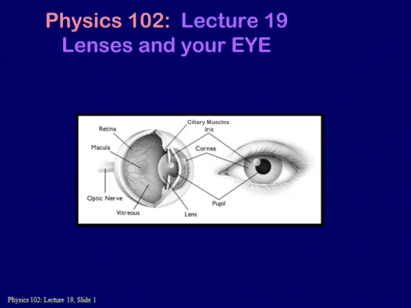
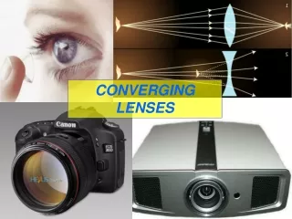
Learn about the types of lenses, how light is refracted, and how to create ray diagrams to visualize image formation with convex and concave lenses.

CONVERGING LENSES
E N D
Presentation Transcript
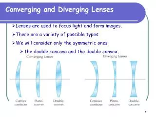
Lenses Lenses REFRACT light and are usually used to form IMAGES 2 types convex concave bi-convex plano-convex bi-concave plano-concave
Actual Draw as Actual Draw as In practice, light is refracted at both surfaces of the lens but for simplicity we draw only one refraction as if it happened at the centre line
Convex FOCUS axis F PARALLEL rays from distant object focal length Convex lenses bring the rays together (‘converge’) at a focus. Convex lenses are CONVERGING LENSES
Concave PARALLEL rays from distant object F F FOCUS (‘Virtual’) focal length Concave lenses spread the rays out (‘diverge’). The rays seem to come from a ‘virtual focus’ on the other side. Concave lenses are DIVERGING LENSES Jump back to ray diagrams Next
Ray diagrams Light is reflected off ALL POINTS of a non-luminous object in LOTS OF DIFFERENT DIRECTIONS To work out what sort of image a lens will produce, we select 2 rays only from the top point of the object: one parallel to the axis one to the centre of the lens
RAY DIAGRAMS:RULES OBJECT (simplified) Image – diagram gives position and size 2F F F 2F focal length 2 x focal length 1. A ray parallel to the axis is refracted through the focus 2. A ray to the centre of the lens passes through undeflected (3. A ray through the focus is refracted parallel to the axis)
RAY DIAGRAMS:IMAGES If image LARGER than object: MAGNIFIED If image SMALLER than object: DIMINSHED MAGNIFICATION = IMAGE HEIGHT OBJECT HEIGHT 2F F F 2F This is: MAGNIFIED INVERTED REAL Mag = 1.25 If image SAME WAY UP as object: UPRIGHT If image UPSIDE DOWN: INVERTED If rays pass through object:REAL If rays only seem to come from object (see diverging lens ):VIRTUAL
IMAGE TYPES Object Image Image Object Image MAGNIFIED UPRIGHT VIRTUAL Image DIMISHED INVERTED REAL REAL images can be PROJECTED ON A SCREEN VIRTUAL images cannot be projected
1. Draw the following on graph paper 2F F F 2F Object pos. Image pos. mag/dim upright/Inverted real/virtual Uses outside 2F at 2F between F & 2F at F inside F 2cm large square 2. Draw an object outside 2F at the position shown and at the size shown 3. Apply the ray diagram rules and draw in the image 4. Classify the image by filling in the table below. Repeat for other positions
1. OBJECT OUTSIDE 2F 2F F F 2F IMAGE: REAL, INVERTED, DIMINSHED uses IMAGEPOSITION: between F and 2F next diagram Arrow key to animate slide
2. OBJECT AT 2F 2F F F 2F IMAGE: REAL, INVERTED, SAME SIZE uses IMAGEPOSITION: at 2F next diagram Arrow key to animate slide
3. OBJECT BETWEEN F AND 2F 2F F F 2F IMAGE: REAL, INVERTED, MAGNIFIED uses IMAGEPOSITION: outside 2F next diagram Arrow key to animate slide
4. OBJECT AT F 2F F F 2F IMAGE: NO IMAGE FORMED (rays don’t meet) uses IMAGEPOSITION: none (or at infinity) next diagram Arrow key to animate slide
5. OBJECT INSIDE F 2F F F 2F Arrow key to animate slide uses *VIRTUAL Image: Light does NOT actually pass through it – cannot be projected onto a screen end show IMAGE: VIRTUAL*, UPRIGHT, MAGNIFIED IMAGEPOSITION: inside 2F & SAME SIDE AS OBJECT