Download
1 / 33
390 likes | 755 Views
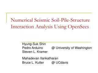
Numerical Seismic Soil-Pile-Structure Interaction Analysis Using OpenSees. Hyung-Suk Shin Pedro Arduino @ University of Washington Steven L. Kramer Mahadevan Ilankatharan Bruce L. Kutter @ UCdavis. Outline. Centrifuge test 1 Bent & Bridge Model Experimental and numerical Results

E N D
Numerical Seismic Soil-Pile-Structure Interaction Analysis Using OpenSees Hyung-Suk Shin Pedro Arduino @ University of Washington Steven L. Kramer Mahadevan Ilankatharan Bruce L. Kutter @ UCdavis
Outline • Centrifuge test 1 • Bent & Bridge Model • Experimental and numerical Results • Centrifuge test 2 • Oriented Bent Model • Experimental and numerical Results • Conclusion
Centrifuge Test 1 1 / 52 scale
Centrifuge Test 1 Shaking direction
Centrifuge Test 1 Shaking direction
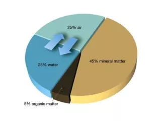
- Nevada sand • Dry soil • Dr = 80 % • Unit weight = 16.29 kN/m3 • ρd = 1.66 Mg/m3 Soil
Northridge 1994 Input motion
p-y spring t-z spring Soil model in OpenSees Pressure dependent multi yield elasto-plastic material model (by Elgamal and Yang) q-z spring Pile model in OpenSees Nonlinear fiber beam column element p Interface spring model in OpenSees 1-D nonlinear springs (by Boulanger) pult (Reese 1974) y y50 (API 1993) Interaction model
Experimental & Numerical Results(Single bridge bent) 2 soil column model
Experimental & Numerical Results(Single bridge bent) Maximum bending moment Ground surface (a) 1 soil (b) 2 soil
Bridge deck equalDOF Two-Span Bridge Model & Simplification
Experimental & Numerical Results(Two-Span Bridge) 0.25g 0.40g (a) short bent (b) long bent (c) medium bent
Increasing intensity Increasing intensity Experimental & Numerical Results(Two-Span Bridge) short bent long bent medium bent short bent long bent medium bent (a) centrifuge (b) OpenSees
Centrifuge Test 2 1 / 52 scale
ax ay axbase Apply absolute freefield motions to a series of p-y springs Decompose base motion Calculate freefield motions based on decomposed base motions Oriented Bent Model & Simplification
3D Bent Structure & Soil axbase* sin() axbase* cos()
Experimental & Numerical Results(free field motion) 0.5m 2.6m 5.9m 21.1m
Experimental & Numerical Results(Oriented Bents – 0o, 30o, 60o, 90o) 0o 30o ax ay1 60o 90o y x z
Experimental & Numerical Results(Oriented Bents – 0o, 30o, 60o, 90o) 0o 30o ax y 60o 90o x z
Experimental & Numerical Results(Oriented Bents – 0o, 30o, 60o, 90o) 0o 30o ay1 60o y 90o x z
Experimental & Numerical Results(Oriented Bents – 0o, 30o, 60o, 90o) -z zz xx yy y x
Experimental & Numerical Results(Oriented Bents – 0o, 30o, 60o, 90o) 0o 30o 60o 90o
Future work Increasing diameter Increasing stiffness
Conclusion • Traditional p-y curves work well for the dynamic soil-pile-structure interaction analysis of dry sand. • Vertical rocking motion of the bridge bent should be included in the analysis to capture the correct structural response. • Simplified coupled bridge models using one soil column for each bent provides a good estimation. • The maximum bending moment of the individual bent in a full bridge occurs at different depths and changes with input motion intensities. • Simplified angled bridge models using decomposed free field motions capture well the primary structural response.
Experimental & Numerical Results(Oriented Bents – 0o, 30o, 60o, 90o) 0o 30o 60o 90o