Download
1 / 13
130 likes | 304 Views
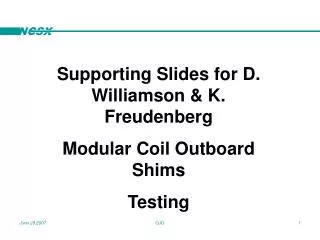
Supporting Slides for D. Williamson & K. Freudenberg Modular Coil Outboard Shims Testing. A traditional tension/compression testing machine has been configure to pull “double shear” combinations. Side rams allow the application of normal (transverse) loads. Friction Testing Setup.

E N D
Supporting Slides for D. Williamson & K. Freudenberg Modular Coil Outboard Shims Testing GJG
A traditional tension/compression testing machine has been configure to pull “double shear” combinations. Side rams allow the application of normal (transverse) loads Friction Testing Setup GJG
A 0.38” thick x 1.00” wide center element receives the application of friction-encouraging medium (alumina, in these cases) Wider (1.50”) side plates are added to each side of the center element with an axial overlap of 1.0” The normal/transverse load (10 kip max) is added at the center of the overlap areas (2 in**2 total area) Typical Test Combination GJG
2nd Design Test Combination • The original design called for a maximum loading of 10 kip over the available area • A choice was made to reduce the test area rather than upgrade the test rig after analysts began predicting 17 ksi loading needs. • The lessened area results in 10 kip max applied on two series ½ in**2 areas (1 in**2 total) GJG
Ellis and Gettelfinger procured two families of alumina on sideplates With and without bondcoat The 3 least desirable friction results were in the “no bondcoat” population admidst desirable results Is the “no bondcoat” correlation a red herring? Observations GJG
Alumina, 2 Constant Pressures, Variable SS Finish *Pre-test cleaning in question **Machine shutdown on software trip GJG
Machining checks show that slowly turning carbide tools may be used without chipping the alumina The slitting saw (used on lower specimen) may be appropriate for trimmable shims Trimmable Shim Feasibility GJG
The Rev. X shim pictured was provided with a 1/16 radius on all edges to possibly avoid alumina fracture at line contact areas. A cost-saving proposal has only hand chamfering to about 0.040”. Shall We Radius? GJG
This alumina-with-bondcoat sideplate was supported in a cast iron welder's vee block (45 degree style) and had a 1" dia platen loaded onto its 1" uppermost edge. The sideplate had edges broken to some arbitrary and probably inconsistent value. The edge survived a 1 kip load without obvious damage. A 2.3 kip (caught by the "instantaneous peak" meter) load resulted in the fracture pictured. Next up – Investigation at small angles: ~0.2 degrees rather than 45. First Rough Inquiry GJG
Alumina Spec, Rev.0 • Thickness 0.012” +0.003/-0.002 • Roughness >100 microinch RMS • Vacuum Bake to 300 C (by PPPL) • Dunk check in LN2 (by PPPL) • Initial Test Population required by spec GJG
Conversation with Incumbent Supplier • Robert Rigney of A&A asserts that normal alumina coatings have surface shear strength of 2-3 ksi. • The nickel aluminide bondcoat increases this to 6-7 ksi. • Roughness is a controllable parameter • Rigney suggests that NCSX considers a larger particle size to achieve the desired rougher surface. • Also suggests that the larger particle would have better “bite in” capability. GJG
Decision Point: Larger alumina particle size Or Use current size Investigate edge loading at flat angles Go to cycle testing Recap GJG